This thread has been locked.

If you have a related question, please click the "Ask a related question" button in the top right corner. The newly created question will be automatically linked to this question.

DP83848I: Interfacing with STM32F765ZGT6 not working

Part Number: DP83848I

Hi,

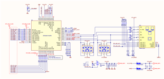
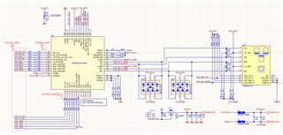
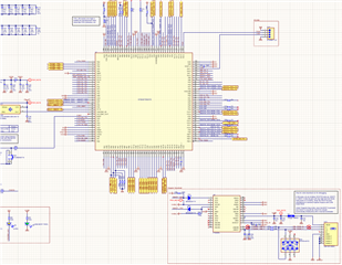
I am interfacing DP83848IVV with STM32F765ZGT6. This design is a new version of old design. In old design I was able to successfully interface the PHY with STM32. But in new design same code is not working. There has been no change in the Ethernet circuit. On CRO, I see that RCC_MCO is 25MHz, and CLK_OUT is also 25MHz. I do not see any 2.5MHz clock on MCO - which means that communication is not working.

Physically circuit is okay and I checked on 3 boards. On all new boards the ethernet is not working. In old board the ETH_RXDx and ETH_TXDx lines were around 96mil. In new board these lines are 106mils. Operating in MII mode.

Please suggest what should be correct way to debug and identify the issues.

  • Hi Mayank,

    Could I asked couple question for further debug:

    • What is the changes did you do between the new design and old design other than the trace width?
    • Could you check 0x0017 register value?

    --

    Thank you,

    Hillman Lin

  • In old revision we used WE-74990101210 and in new revision we are using WE-7499011222A

    I will revert with 0x0017 by tomorrow. 

  • There is not external or MCU internal pullup resistor configured on MDIO. Can this be a problem? Problem is that there is no clock observed on MDC. 

  • Hi Manyank,

    This could be a problem on the MDIO communication. But is shouldn't effect the MDC clock. If you are not able to see MDC clock, that might be the problem on the processor. Could you double check on the processor make sure it generate clock?

    --

    Regards,

    Hillman Lin

  • I tried better arrangement for CRO probes and I am able to confirm 2.16 Mhz clock on MDC and correct MDIO commands being sent from MCU.

    In response the MDIO stays High for next 18 clock pulses - which results error reading of 65535.

    PHY Address: 00h, PHYBCR: 00h

    As per circuit shared earlier, there is no  pullup or pulldown resistors for assigning PHY address - the system is working on default PHY address which I am assuming should be 0. (also as per working code)

    I tried reading PHYCR register but the command again returns 65535 because MDIO read command is sent to PHY address 0.

    Another thing that confuses me is that PHY Address 0 means MII Isolate Mode and in MII Isolate mode there will not data transfer. But old H/w design and same code works there.

    Is there any better way to read the address stored n PHY.

  • I solved the problem, changed the device ID to 1 from 0. It still remains unclear why on old hardware the code still works with ID 0 and on new hardware it works with ID 1. It is exactly the same part number. 

  • Hi Mayank,

    Glad you solve the issue :)

    --

    Regards,

    Hillman Lin