This thread has been locked.

If you have a related question, please click the "Ask a related question" button in the top right corner. The newly created question will be automatically linked to this question.

THVD8000: Design review of Power over RS485 circuit

Part Number: THVD8000

Hi ,

  I am using THVD8000 Driver IC for my new project to power nodes from gateway device over two wire.

The scope of project is 

1. Gateway can have maximum of 3 nodes and minimum of 1 node connected on Power over RS485 bus at any point of time .

2. Gateway gets powered from 24V AC/DC powerline and rectifies this power to 24VDC which gets supplied to nodes over 2 wire.

3. A single node can consume maximum of 120mA from the bus (2.88W)

4. the cable used would be 18AWG untwisted, unshielded with maximum length of cable at 300ft .Cable part no's similar to below link will be used

  https://www.supplyhouse.com/Honeywell-Genesis-47114807-500-ft-18-3-Solid-CL2-PVC-Honeywell-Genesis-Thermostat-Cable?utm_source=google_ad&utm_medium=Shopping_tm&utm_campaign=Shopping_TM_New_users&gclid=Cj0KCQiAx6ugBhCcARIsAGNmMbiFMfnGf6dk33mlNu8Et5YdO3bvpY1-B8tHupA_Kk2sRelJUIpXvvsaAovnEALw_wcB

5. The bus wires may run close to 230V power lines in conduits.

6. The nodes and gateway communicate at 9600 baud. The OOK carrier frequency is set to 130K

7. Attached is my circuit schematics, L8 and L10 are 2.2uH inductors(https://www.digikey.com/en/products/detail/bourns-inc/RLB1112V4-222J/6236173)

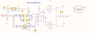
Please review the schematics and let me know of any improvisations required before prototyping.

  • Hi Sajul,

    Thanks for reaching out!

    So I have a few comments on the schematic:

    1. Modulation Frequency Selection: While you can try to select 130KHz for the modulation frequency the actual frequency may deviate up to +/-25% as well as the addition of a 30KHz spread spectrum clocking signal. There isn't anything wrong with the design from this point of view but I wanted to emphasize that it isn't super precise - but the data rate you are using is fine with the selected modulation frequency.

    2. Series Capacitor Selection: The capacitor minimum for the series connection between THVD8000 and shared power/data bus is ~245nF - since you have chosen 470nF you should be in the clear on the value. One thing to note is that the voltage rating for ceramic should be about 2x what is seen from the cap to prevent significant capacitance derating. So for this application 50V rated caps would be suggested.

    3. Inductor Selection: The minimum inductance per power node at 130KHz in a terminated system, with a maximum of power nodes of 3 loads + 1 power source is ~1.87mH of effective inductance per power node. With 3 power loads and 1 power source (if it is 2 power loads and 1 power source the idea is similar but the inductance requirements aren't as high) with a max of 120mA per node is 360mA max from the power source - based on quick estimates - the inductors chosen will see a very small inductance drop. From the 2.2mH chosen. The minimum effective inductance per node is going to be 1.87mH with 4 nodes (3 loads + 1 source) or 1.39mH (2 loads + 1 source) as I am a little unclear the exact setup - but either setup will work with these inductors under this use case.

    4. Its a bit hard to tell from the cable data sheet - but there could be some potential reflections due to characteristic impedance mismatch between termination resistor and cabling. However this effect should be pretty small as the total electrical length of the system is long w.r.t. signals wavelength so some of the higher harmonics of the data signal may be more susceptible to reflections. Unfortunately with many thermostat wiring applications the cabling is hard to tune - but generally the bus is short enough where its not that big of an issue - which I suspect will be the case in your application.

    5. Termination: If there are more than 2 THVD8000's on the bus - only the two terminal ends of the bus should be terminated - at most 2 120 ohm terminations should be used.

    6. Protection: There isn't any protection in case of surge/transients. The THVD8000 really is meant to be used under standard RS-485 conditions - -7V to 12V common mode range. Any higher transients or possible surges could destroy the IC. Especially with the 230V power line close to the system I'd strongly suggest additional surge and/or transient protection diodes on the communication nodes. This doesn't completely remove risk - to mitigate the maximum amount of risk the addition of an additional line driver on the output of the THVD8000 + Transformer to create isolation between high voltage share buses and the lower voltage power nodes - we do have an application note on that use case in case you want to see some examples of higher voltage implementations. https://www.ti.com.cn/cn/lit/an/slla590/slla590.pdf?ts=1678723300005  . The 0 Ohm series resistors also may want to be protected by thick film or wire wound pulse proof resistors to help protect against transients from the bus.

    I think overall you have a real good start here - I think the biggest concern I have is the lack of protection for the communication node when you are running it very close to a high voltage line. I think these issues can be mitigated rather easily however. 

    Please let me know if you have any other questions!

    Best,

    Parker Dodson