This thread has been locked.

If you have a related question, please click the "Ask a related question" button in the top right corner. The newly created question will be automatically linked to this question.

DS90UB929-Q1: I2C communication problem

Part Number: DS90UB929-Q1
Other Parts Discussed in Thread: TFP410, ALP, USB2ANY

Dear all,

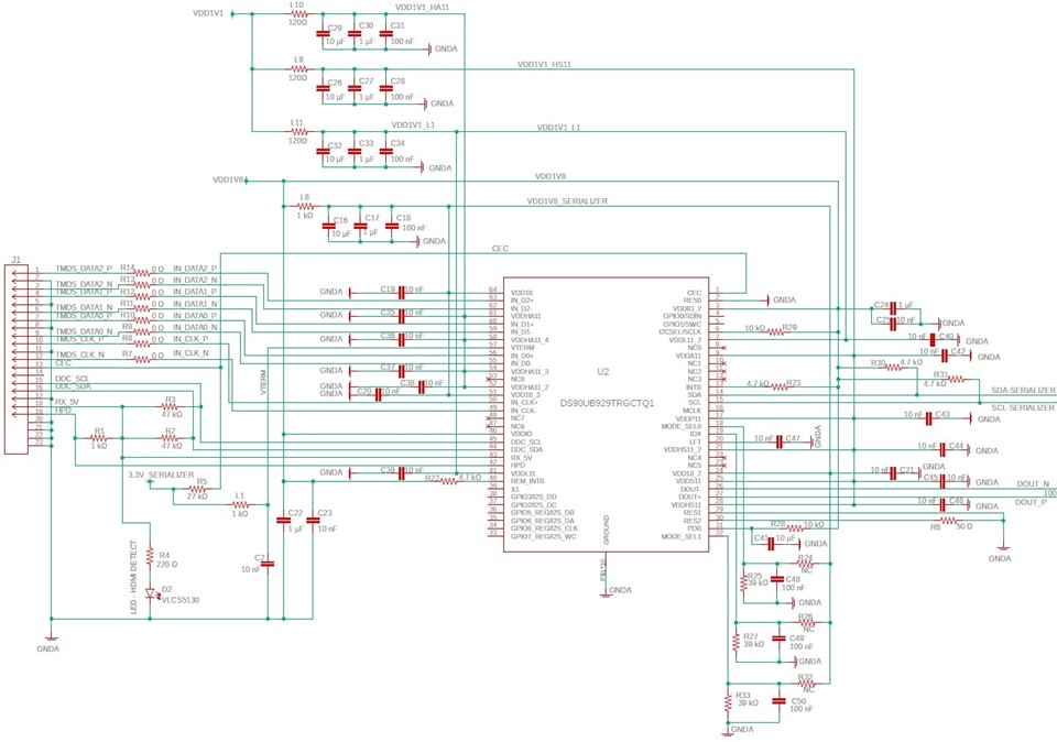
I'm trying to configure a DS90UB929 device via I2C interface by using a microcontroller. The micrcocontroller is defined as the master device and when I'm sending the address word to the DS90UB929 device, I never received ACK signal from the 929.

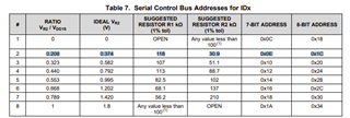
ID voltage level is 0V (using 40 kOhm resistor pull down), so 929 adresse should be 0x18 for write operation.

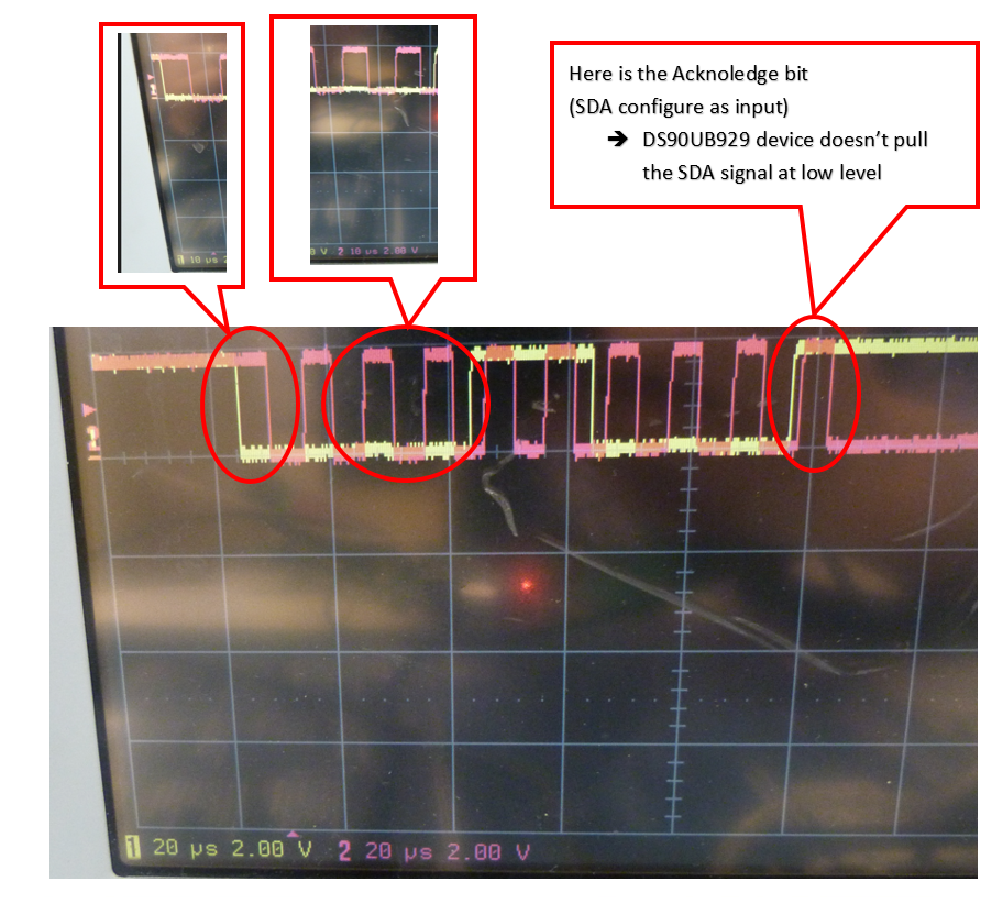
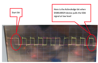
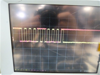
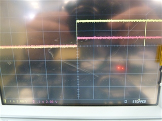
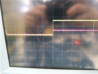
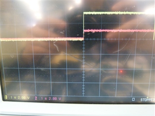
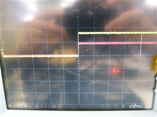
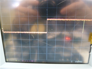
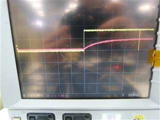
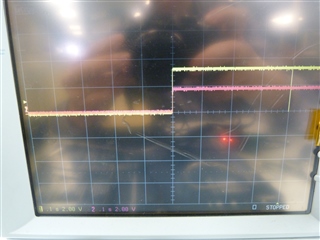
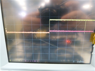
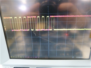
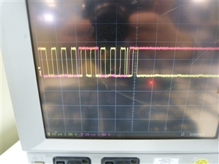
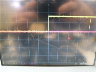
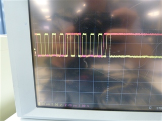
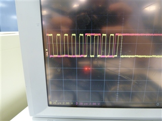
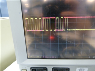
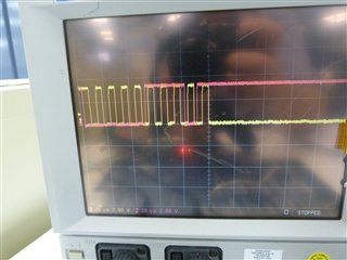
Here is a screen copy of the I2C bus :

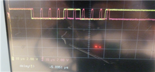
--> Normally, the SDA signal (yellow curve) should be pulled down to 0V during the nineth clock cycle.

On the picture, when SDA is configure as an input, the voltage level is 1.8V because of pull-up resistors (4.7 Kohm)

Could you, please help me to understand why it doesn't work ?

Per advance thank you

Best regards

Mickael C.

  • Hi Michael,

    I have some follow up questions:

    • Are you using an EVM or a custom PCB?
    • Can you probe the PDB pin and voltage rails to make sure the device is powered on correctly?
    • Can you share the schematic?
    • What I2C rate are you using?

    Regards,

    Ben

  • Hi Ben,

    I'm using a custom PCB (with 100 ohms characteristic impedance for high data rate lines)

    Please find the schematic used to monitor the DS90UB929 with SDA_SERIALIZER and SCL_SERIALIZER signals.

    As you can see, PDB pin is pulled-up to 1.8V power supply.

    I have tried with 200 KHz and 7 KHz clock rate for I2C dialog. The problem is the same with these 2 rates.

    Regarding I2C monitoring for both SCL and SDA signals :

    - I configure pin as output and applied 0V for low level.

    - I configure pin as input for high level (level is high thanks to 4.7 Kohms pull-up resistors) .

    Best regards

    Mickael C.

  • Hi Mickael,

    Can you check the high and low times of SDA and SCL? It is possible these are too short. See the datasheet for spec.

    Regards,

    Ben

  • Hi Ben,

    I have adjusted timing signals for both SDA and SCL signals for I2C clock rates at 100 KHz :

    Unfortunately, it doesn't work.

    Don't you think my problem is due to multi-master communication as DS90UB929 device should be a master device for I2C communication?

    For comparison, I have catched I2C signals used on the Evaluation board of this device :

    Mickael C.

  • I have also tried using 3V3 for I2C power supply :

    Same result : DS90UB929 doesn't send any ACK signal

    Mickael C.

  • Hi Mickael,

    Can you probe several point to check the voltage?

    • IDx pin
    • VDDIO
    • VDD11
    • PDB

    In context of the power up sequence, when are you sending this I2C transaction?

    Regards,

    Ben

  • Hi Ben,

    Thanks for your helpful support

    - Here is voltage VDD1V1-HA11 (pink curve) compare to the clock falling edge of the first start bit (yellow curve) : 0.4 second between the 1V1 power on on the device and the beginning of I2C dialog

    - Here is voltage VDD1V1-HS11 (pink curve) compare to the clock falling edge of the first start bit (yellow curve) : 0.4 second between the 1V1 power on on the device and the beginning of I2C dialog 

    - Here is voltage VDD1V1-L11 (pink curve) compare to the clock falling edge of the first start bit (yellow curve) : 0.4 second between the 1V1 power on on the device and the beginning of I2C dialog 

    - Here is voltage VDD1V8 (pink curve) compare to the clock falling edge of the first start bit (yellow curve) : 0.4 second between the 1V8 power on on the device and the beginning of I2C dialog 

    - Here is voltage VDDIO (3.3V) (pink curve) compare to the clock falling edge of the first start bit (yellow curve) : 0.4 second between the 3V3 power on on the device and the beginning of I2C dialog 

    - Here is voltage PDB (pink curve) compare to the clock falling edge of the first start bit (yellow curve) : 0.2 second between the PDB high level and the beginning of I2C dialog 

    - Here is voltage INTB (pink curve) compare to the clock falling edge of the first start bit (yellow curve) : 0.4 second between the INTB high level and the beginning of I2C dialog 

    - Here is voltage I2SEL (pink curve) compare to the clock falling edge of the first start bit (yellow curve) :

    Unfortunately, I2C communication doesn't work : (signals were tested on the DS90UB929 pin)

    I'm sorry but I'm really don't know what is wrong with I2C dialog.

    As I was suspected a multi-master communication problem, I have made some trials using clock stretching detection.

    But there is always the same dialog problem, and it seems that DS90UB929 doesn't use clock stretching (SCL is pulled-up when SCL pin is configure as input).

    It acts as if the device is not monitoring I2C bus.

    Mickael C.

  • Hi Mickael,

    It looks like the IDx pin is actually at 0.2V, which would mean the address might be 0x1C rather than 0x18:

    Is the pullup depopulated for this pin?

    Also it may be worth double checking to make sure your controller uses 8-bit addresses, it may need to use the 7-bit address instead.

    Regards,

    Ben

  • Hi Ben,

    Sorry, I have forgotten to send you the IDx voltage level yesterday :

    Here is voltage IDx (pink curve) compare to the clock falling edge of the first start bit (yellow curve) :  There is no pull up resistor on the IDx pin, so voltage level is 0V

    Following your proposal, I have mde some trial with different address values :

    First trial with address 0x18 :  START 0 0 0 1 1 0 0 0 ACK

    Second trial with 0x0C : START 0 0 0 0 1 1 0 0 ACK

    Third trial with 0x1C : START 0 0 0 1 1 1 0 0 ACK

    Last trial with 0x0E : START 0 0 0 0 1 1 1 0 ACK

    Unfortunately, always the same problem : no acknoledge.

    Mickael C.

  • Hi Ben,

    I have made a small software to test all even addresses (0x00, 0x02, 0x04 .. up to 0xFE) and check Acknoledge bit.

    I send following order on I2C bus using 8-bit address (a7 a6 a5 a4 a3 a2 a1 a0) : START  a7 a6 a5 a4 a3 a2 a1 a0 ACK STOP

    With TFP410 device (an other device on the board but monitored with different I2C bus), it works well.

    With 929 device, it never responds correctly ! It acts as if there is no device on the I2C bus. I have double-checked wiring of DS90UB929 and all pins are well connected to the board.

    Do you have any idea - What configuration can make DS90ub929 device locked like that ?

    Per advance thank you

    Mickael C.

  • Hi Mickael,

    Do you have any idea - What configuration can make DS90ub929 device locked like that ?

    Usually this would be because of a wrong connection of some sort. But from the schematic, everything looks to be okay. It may have to do with the power-up sequence. Can you capture the power sequence so we can check if it matches what is in the datasheet?

    Is it possible for you to tap the I2C directly and use a USB2ANY and ALP to see if that is capable of communicating to the device?

    Also, have you connected this 929 to a DES yet? If so, can the DES access the 929 remotely?

    Regards,

    Ben

  • Hi Ben,

    I will do a second prototype to check if I see the same behavior of I2C dialog with the 929 device. I will also try to tap I2C wires and use USB2ANY and ALP software to check I2C communication. I will keep you inform.

  • Hi Mickael,

    Thanks.

    Regards,

    Ben