This thread has been locked.

If you have a related question, please click the "Ask a related question" button in the top right corner. The newly created question will be automatically linked to this question.

TPD2E001: VCC pin

Part Number: TPD2E001

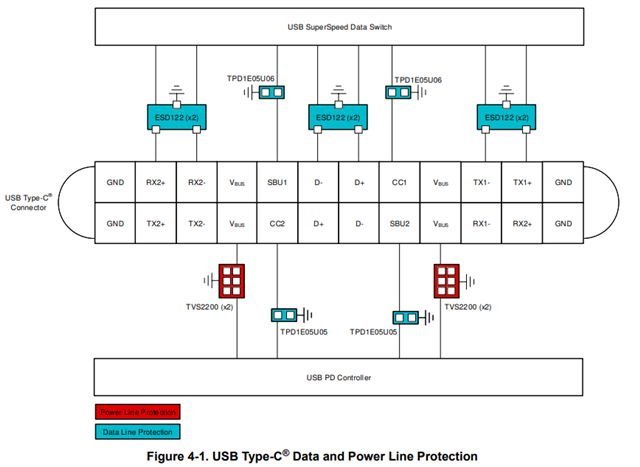
We're wondering where the ESD protector of TPD2E001 connects to for type-C connector? From diagram below, is it connected to SA5V_3 or SA5V for VCC pin of TPD2E001

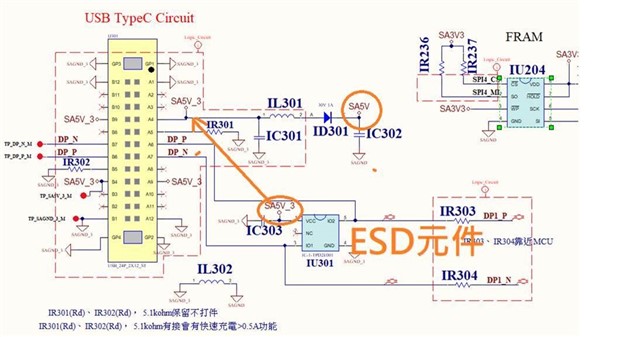
Is TPD2E001 optimized for Type C application? or other suggestion? thanks. 

  • Hi Brian,

    From the schematic it shows the Vcc pin of TPD2E001 is connected to net SA5V_3.

    The Vcc pin is for protecting the Vbus line for USB. There are newer devices in different channel counts that offer better overall performance and might make your layout simpler. 

    I'd suggest going through the USB ESD/Surge Protection app note for multiple recommendations by USB type (2.0, 3.0, etc.). 

    Regards,

    Sebastian 

  • Thanks. My question is that where on the circuitry of SA5V and SA5V_3 the TPD2E001's VCC pin needs to connect? Which is better for ESD protection?

    Regards

    Brian

  • Hi Brian,

    Apologies for the miscommunication, I would just connect the Vcc pin to the SA5V_3 power supply node. The ESD diode GND should be the same GND as the connector. SA5V and TPD2E001 share different grounds so it would not be optimal for dissipating ESD currents.

    Regards,

    Sebastian 

  • The SAGND_3 and SAGND connection on PCB are seprated by Bead core. 

    有Bead 隔開

    Here are more info. to this question. 

    From typeC ESD's prospective, the ESD component's VCC needs to connect to SA5V_3 rather than SA5V, correct?

    IL301、IL302: Bead Core for noise immunity improved.

    ID301 For reverse power protection

    IC301: Capacitor for filter

  • Hi Brian,

    In order to optimize ESD protection, you want to provide the lowest impedance path to ground. If you have a shielded connector, it's best to make a direct connection between the shielding and chassis ground (if available) or to the ground plane. This will create a very low impedance path to ground that prevents energy in an ESD event from reaching a protected component.  

    The ferrite bead protects the IC from DC voltages between GNDs, but the DC connection provided by the ferrite bead can introduce unwanted DC ground loops and may not be suitable for high-resolution systems. 

    To optimize ESD protection I would connect to SA5V_3 as it provides the lowest impedance path to ground in the current layout. 

    Regards,

    Sebastian