This thread has been locked.

If you have a related question, please click the "Ask a related question" button in the top right corner. The newly created question will be automatically linked to this question.

DS90UB954-Q1: SerDes configuration not robust in low temperature situation

Part Number: DS90UB954-Q1
Other Parts Discussed in Thread: DS90UB953-Q1

Dear TI experts,

we have a setup where a camera (SONY IMX390 sensor) with connected through Serdes (DS90UB953-Q1/ DS90UB954-Q1) to an ECU.

During tests where (only!) the camera is in a climate chamber at -30°C, we saw problems in I2C communication through the back channel.

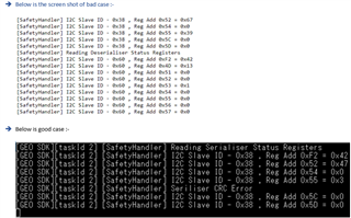
Serializer status register 0x52 showed a number of CRC errors, also the LOCK pin was sometimes lost.

Does anyone have experience to make SerDes configuration more robust for low temperature situations?

This configuration we are currently using:

//////////////////////////////////////////////////
//
// deserializer DS90UB954-Q1 settings
//
//////////////////////////////////////////////////

{ 0x4c, 0x01 }
{ 0x33, 0x01 } // Gated clock, 4-lane
{ 0x0c, 1) } // Enable port 0 receiver only
{ 0x20, 0x20 } // Forwarding enabled for RX Port 0 only
{ 0x42, 0x71 } // Default value

{ 0x5C, I2C_ADDR_SERIALIZER }
{ 0x5D, 0x34 } // IMX390 slave address
{ 0x65, 0x42 }
{ 0x58, 0x5E }
{ 0x6d, 0x7C }
{ 0xD2, 0x54 }
{ 0xD5, 0x80 }
{ 0x41, 0xC9 }
{ 0x7c, 0x00 }

{ 0x0F, 0xFF } // GPIOx Input Enable
{ 0x12, 0x00 } // Select GPIO2 as input
{ 0x6F, 0x8A } // BS GPIO2 : FrameSync signal
{ 0x18, 0xa0 } // External FrameSync from GPIO

// Handle EEPROM on the camera module
{ 0x66, 0xA0 } // SlaveAlias[1]: EEPROM0 slave broadcast address
{ 0x67, 0xA2 } // SlaveAlias[2]: EEPROM1 slave broadcast address
{ 0x5E, 0xA0 } // EEPROM0 slave address
{ 0x5F, 0xA2 } // EEPROM1 slave address

{ 0x01, 0x01 }

// Wait for Deserializer to reacquire Lock and Pass


//////////////////////////////////////////////////
//
// serializer DS90UB953-Q1 settings
//
//////////////////////////////////////////////////

{ 0x05, 0x08 } //CSI-2 Synchronous Mode
{ 0x02, 0x33 } // 4-lane


// setting to provide 25MHz INCLK to sensor
{ 0x06, 0x21 } // DIV_N_VAL
{ 0x07, 0x50 } // HS_CLK_DIV & DIV_M_VAL

// GPIO2 - frame sync; GPIO3 - reset
{ 0x0d, 0x40 }
{ 0x0e, 0x84 }
{ 0x0d, 0x48 }
{ 0x0e, 0xc0 }

// TODO: optimize clock based on Sensor SCL tHIGH/tLOW requirements
{ 0x0B, 0x18 }
{ 0x0C, 0x18 }

Thanks and kind regards,

Lennart

  • Hello Lennart,

    can you provide register dumps from SER and from DES, during cold (abnormal) and in during a good case!

  • Hi Hamzeh,

    Please see the screenshot of the register dumps taken from our colleague.. he is still going to take some new readings and post it in this thread.

  • Hi Romel,

    Please provide a full register dump of des and ser for us to take a look. 

    Glenn 

  • FullRegDump.xlsx

    In bad case scenario in -30 degrees, Seriliser is not accessible most of the time. However, I read the registers by retrying read command. Please see excel sheet for full dump of serialiser and deserialiser.

  • Hi Vikas,

    Thanks for providing this register dump. Included some feedback below:

    • Lock loss was observed on the "good" case with register 0x4D on the des reading 0x13, seems like there's issues in both situations?
    • Register 0xD3 of the deserializer does not appear to have an AEQ code locked, are we doing something unique with the initialization here?
    • As you mentioned, serializer registers 0x55 and 0x56 both show CRC errors in the back channel. However these are present in both the "good" and "bad" register dumps.

    Overall it would be great to understand what's going on at the hardware level here. Do you have a copy of the schematic for the SER & DES which we could take a look at?

    I'm also curious why there's no AEQ code read back in register 0xD3. Is this a unique situation where we have a very short cable? If so, have we run tests with different cable lengths?

    Best,

    Thomas

  • DES_ckt.pdfSER_ckt.pdf

    Hi Thomas,

    please find attached SER and DES circuit.

    Regards,

    Romel

  • Hi Romel,

    I have taken a look at the schematics: 

    1. Can you confirm that the power supply pin specifications are all being met for the 954 and 953? The ferrite beads and capacitor values at some of the power pins deviate from the recommendations in the Typical Application diagram.
    2. It looks like you are using custom POC networks on the 953 and 954 since the components do not exactly match the ones in the datasheet. Can you confirm that the POC networks meet all requirements (channel specifications, POC noise, frequency range, etc.)? 
    3. I did not see any pull-up resistors on the I2C_SCL and I2C_SDA pins. Please ensure that the appropriate pull-up resistors are present. 
    4. Have you checked whether the power-up sequence is being followed for both the DS90UB953 and DS90UB954? In the 953 schematic, the PDB pin capacitor is 1uF, but it should be >10uF. If you are controlling the PDB pin using HW control, >10uF is recommended to ensure that PDB powers up after all the power supplies on the board have stabilized.

    Can you also share what cable length you are using and whether you have tested other cables as well?

    Regards,

    Cindy 

  • Hi CIndy,

    Please see my answers to your questions below

    1. Yes, DC levels and peak-to-peak noise levels of all 3 power supply pins (in the camera) are within specifications. Although the VDD peak-to-peak noise level at -40C is close to the 25mVpp max level at ~24mVpp, the other 2 more critical power supplies are well within the limits (VDD_PLL=~15mVpp, VDD_DRV=~8mV).
    2. The custom POC meets all the specifications.
    3. The I2C pull-up resistors are on a different schematics page.
    4. Even if the capacitor in the RC delay circuit is less than 10uF, the actual delay on the PDB pin still meets the requirement. Please see details below

    The cable we use in the test is ~1.5m - 2m long.

    Regards,

    Romel 

  • Hi Romel,

    1. I noticed in your script that you are setting 0xD5 AEQ_MIN_MAX to 0x80 from the default value of 0xF2. It is recommended to leave the maximum EQ level at 14, as higher EQ levels are more effective for cables with greater degradation. Can you try changing 0xD5[4:7] to 0xF and see if this improves your results? After modifying the minimum or maximum positions, set AEQ_RESTART(0xD2[3]) to 1 to restart the AEQ process.
    2. Have you tried testing with different cables or a different camera module?

    Regards,

    Cindy

  • Hi Cindy, 

    We did the change suggested by you. D5 = 0xf2 and AEQ_RESTART. Unfortunatly, that did not work. Below is the deserialiser dump after the change.

    De-serialiser
    0 60
    1 0
    2 1E
    3 20
    4 DF
    5 1
    6 0
    7 FE
    8 1C
    9 10
    A 7A
    B 7A
    C 81
    D B9
    E A
    F 7F
    10 0
    11 0
    12 0
    13 0
    14 0
    15 0
    16 0
    17 0
    18 A0
    19 0
    1A 0
    1B 0
    1C 0
    1D 0
    1E 4
    1F 2
    20 20
    21 1
    22 0
    23 0
    24 0
    25 0
    26 0
    27 0
    28 0
    29 0
    2A 0
    2B 0
    2C 0
    2D 0
    2E 0
    2F 0
    30 0
    31 0
    32 0
    33 1
    34 40
    35 1
    36 0
    37 1
    38 0
    39 0
    3A 0
    3B 1
    3C 14
    3D 6F
    3E 0
    3F 40
    40 0
    41 C9
    42 71
    43 1
    44 0
    45 0
    46 0
    47 0
    48 0
    49 0
    4A 0
    4B 12
    4C 1
    4D 13
    4E 45
    4F 64
    50 0
    51 0
    52 0
    53 4
    54 0
    55 0
    56 0
    57 0
    58 5E
    59 0
    5A 0
    5B 30
    5C 38
    5D 34
    5E A0
    5F A2
    60 0
    61 0
    62 0
    63 0
    64 0
    65 42
    66 A0
    67 A2
    68 0
    69 0
    6A 0
    6B 0
    6C 0
    6D 7C
    6E 88
    6F 8A
    70 2B
    71 2C
    72 E4
    73 4
    74 5A
    75 12
    76 E8
    77 C5
    78 0
    79 1
    7A 0
    7B 0
    7C 0
    7D 0
    7E 0
    7F 0
    80 0
    81 0
    82 0
    83 0
    84 0
    85 0
    86 0
    87 0
    88 0
    89 0
    8A 0
    8B 0
    8C 0
    8D 0
    8E 0
    8F 0
    90 0
    91 0
    92 0
    93 0
    94 0
    95 0
    96 0
    97 0
    98 0
    99 0
    9A 0
    9B 0
    9C 0
    9D 0
    9E 0
    9F 0
    A0 2
    A1 F
    A2 0
    A3 0
    A4 8
    A5 19
    A6 0
    A7 0
    A8 0
    A9 0
    AA 0
    AB 0
    AC 0
    AD 0
    AE 0
    AF 0
    B0 8
    B1 14
    B2 3F
    B3 8
    B4 25
    B5 0
    B6 18
    B7 0
    B8 8C
    B9 33
    BA 83
    BB 74
    BC 80
    BD 0
    BE 0
    BF 0
    C0 0
    C1 0
    C2 0
    C3 0
    C4 0
    C5 0
    C6 0
    C7 0
    C8 0
    C9 0
    CA 0
    CB 0
    CC 0
    CD 0
    CE 0
    CF 0
    D0 0
    D1 43
    D2 54
    D3 2
    D4 60
    D5 F2
    D6 0
    D7 2
    D8 0
    D9 0
    DA 0
    DB 0
    DC 0
    DD 0
    DE 0
    DF 0
    E0 0
    E1 0
    E2 0
    E3 0
    E4 0
    E5 0
    E6 0
    E7 0
    E8 0
    E9 0
    EA 0
    EB 0
    EC 0
    ED 0
    EE 0
    EF 0
    F0 5F
    F1 55
    F2 42
    F3 39
    F4 35
    F5 34
    F6 0
    F7 0
    F8 0
    F9 0
    FA 0
    FB 0
    FC 0
    FD 0
  • Hi Vikas,

    Have you tried testing with different cables or a different camera module?

    Have you been able to do the above test to rule out a hardware issue?

    Also, can you confirm that you have you measured the IL/RL parameters of the system to ensure it is meeting the FPD-Link channel specifications?

    Regards,

    Cindy

  • Hi Cindy,

    We have performed the marginal analysis on our board. Can you please advice the optimum settings that we can use based on this result? Looking forward on your quick feedback.

    Regards,

    Romel

  • Hi Romel.

    Let me take a look and provide feedback in the next few days.

  • Hi Romel,

    Is this just one system failing or multiple? 

    Glenn 

  • Hi Glen,

    We have multiple system that is failing

    Romel

  • Hi Romel,

    It looks like your system is passing the MAP tool. You may try to program the min/max values of the strobe and EQ registers (0xD5 and 0x41) based on your MAP results to see if there are any improvements. Please refer to page 8 of this MAP tool app note to see an example of how to set these registers. In general, TI recommends to set the minimum EQ level to the lowest EQ level with four valid strobe positions (0 in your case). TI also recommends to leave the maximum EQ level at 14. The strobe position minimum and maximum should be set such that the majority of EQ levels have four valid strobe positions (looks like position 6 to 10 based on your result).

    Regards,

    Cindy