This thread has been locked.

If you have a related question, please click the "Ask a related question" button in the top right corner. The newly created question will be automatically linked to this question.

TUSB212: Schematic review

Part Number: TUSB212

Hi Team,

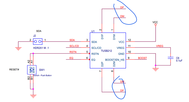
Could you help to check the schematic? There seems to be a issue with the connection of pin2/1 and pin 7/8, please help to check.

The same label is used in the schematic of the TUSB212 EVM, which may confuse customers.

TUSB212 Evaluation Module

Regards

Hailiang

  • Hi Hailiang,

    Going by the schematic, it looks like the DP and DM lanes are shorted to each other, which is correct for having the device boost the signal. One thing I noticed is that there are resistors located on the D1P and D1M lanes. What are those resistors being used for?

    Does NO_ASSY=TRUE mean that the component is not being implemented?

    What issue are you seeing with pins 1/2 and 7/8? Is the signal not being boosted? 

    Please let me know.

    Thanks,

    Ryan

  • Hi Ryan,

    Could you please help me confirm whether r2646 can be changed to 26.7k ohms? Thanks!

    which is correct for having the device boost the signal

    May I ask how to achieve boost? Please help analyze the principle. Will there be a delay between the D1PM and D2PM signals? Thanks!

    Regards,
    Hailiang

  • Hi Hailiang,

    Could you please help me confirm whether r2646 can be changed to 26.7k ohms? Thanks!

    We recommend that pull-up/down resistors for DC Boost pins be between 22K-47KOhms, so 26.7KOhms should be fine, yes.

    May I ask how to achieve boost? Please help analyze the principle. Will there be a delay between the D1PM and D2PM signals? Thanks!

    Signal boosting is achieved by injecting current into a high-speed signal as it goes through the redriver. The amount of boost is determined by the settings used for the BOOST and EQ pins. Signal boosting is not applied to low-speed or full-speed signals, only high-speed signals.

    If the trace is correctly length matched with the D1P/M and D2P/M pins shorted together underneath, then there should be no delay added to the signal after going through the redriver.

    Please let me know if you have any other questions.

    Thanks,

    Ryan