This thread has been locked.

If you have a related question, please click the "Ask a related question" button in the top right corner. The newly created question will be automatically linked to this question.

THVD1424: What is the maximum power rating?

Part Number: THVD1424

Hi team,

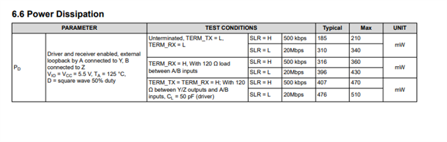
What is the maximum power rating of this device?
Customers are concerned about the small size and integrated termination resistors.

Regards,

Goto

  • RθJA is quite low. Assuming a current of 27.5 mA, the power dissipation is about 91 mW, which results in a temperature increase of about 4 °C above ambient.

    Due to the thermal pad, QFN devices would allow more power dissipation than other packages. (The thermal pad was originally needed for switching power supplies; in applications like this, it is not really necessary.)

  • Hi Goto,

    The maximum power rating of the device is going to be variable with ambient temperature and system setup (as system setup will impact thermal impedance values).

    For a quick approximation please see below - but keep in mind that the thermal impedances will change in customer system. 

    The max junction temperature is 150C - this is related to ambient temperature through the equation TJ = TA + (P*RθJA) where TA is ambient temperature and P is power.  

    RθJA on this device is 46.1 C/W - so to solve for max power P = (TJ-TA)/RθJA

    Which gives this approximate table:

    TJ (C) TA (C) RθJA (C/W) P (max) (W)
    150 -40 46.1 4.121475054
    150 -20 46.1 3.687635575
    150 0 46.1 3.253796095
    150 25 46.1 2.711496746
    150 40 46.1 2.386117137
    150 60 46.1 1.952277657
    150 80 46.1 1.518438178
    150 100 46.1 1.084598698
    150 125 46.1 0.542299349

    And if you compare that  to the measured power dissipation from this device:

    You see that measured Pd is less than max Pd that we approximated from the thermal impedance so its extremely unlikely that power dissipation will be a huge issue with this device because of the lower thermal impedance.  This device also does have a thermal shutdown feature if   junction temperature is exceeded (typically at 170C - but can trip at 150C - be mindful that you shouldn't let the part TJ go above 150 - but if it does this feature is here)

    That being said - thermal parameters will change based on system and layout - so all these values are approximations - for more information on the thermal metrics please see:https://www.ti.com/lit/an/spra953c/spra953c.pdf?ts=1699456637898  .

    Please let me know if you have any further questions!

    Best,

    Parker Dodson 

  • Hi Parker,

    Thanks for your detail explanation!

    Customers want to know how do you package two 120 Ω registers in small chip.
    (They recognize that  this level of resister is typically 6.3 x 3.2 mm.)

    Could you please let me know?

    Best regards,

    Goto

  • On-die resistors are not separate components, and are much smaller (see eesemi.com/resistor-fab.htm). This implies that they are not as robust as external ones. (The absolute maximum ratings allow at most ±6 V over the termination.)

  • Hi Goto,

    Clemens is correct - they are not separate components and are less robust (as mentioned due to the max of +/-6V over the termination) than standard resistor. 

    Essentially the trade off that you can't burn as much power over the terminations as you could theoretically with an external resistor - but in most applications you shouldn't really be too concerned with that large of differentials under normal operating conditions (that would be most likely a fault case to begin with.)

    Please let me know if you have any other questions!

    Best,

    Parker Dodson