Because of the Thanksgiving holiday in the U.S., TI E2E™ design support forum responses may be delayed from November 25 through December 2. Thank you for your patience.

LMH0302: SD-SDI Video Unlocked

Part Number: LMH0302
Other Parts Discussed in Thread: LMH0344, LMH0346

Tool/software:

Hi everyone. This is my first post, so please be patient if I make any mistakes.

My team designed two years ago a board to interface 3G-SDI inputs and outputs, with this part (LMH0302) used to drive the output. I am know testing the board with a Tektronix Waveform Monitor, and all I get is that signal is unlocked, even when the signal is a SD-SDI (576i).

After reviewing the design, I have discovered many issues about the layout, that could become a problem for 3G-SDI. But, is so critical the layout for SD-SDI? If not, what could be the problem so?

Inputs don't work either. We have used LMH0344 and LMH0346, and LMH0344 does not detect well when there is a signal.

I attach you the schematic. I don't think so, but maybe there is an issue there.

Thank you in advance.

Kind Regards.

/resized-image/__size/320x240/__key/communityserver-discussions-components-files/138/Output-SDI-Schematic.png

  • Hi Tomas,

    Nice to meet you. Can you resend the schematic with a higher resolution photo? I cannot see the one you have sent.

    When you use the LMH0346 reclocker does the Lock Det pin go high or is it that the Tek waveform monitor cannot lock to the signal?

    Best,

    Nick 

  • Hi Nick,

    I  have uploaded a new picture. This seems to be better. I don't know why looses so much resolution when I upload it.

    We have reclocker only in the inputs, not in the outputs. Maybe this can cause that Tek waveform monitor receives unlocked signal?

    /resized-image/__size/640x480/__key/communityserver-discussions-components-files/138/pastedimage1730112904006v1.png

  • Hi Tomas,

    Can you send a block diagram of your application to give me a better understanding of the test setup?

    Best regards,

    Nick

  • Hi Tomas,

    Can you send a scope shot on the output of the LMH0302 as well?

    Best,

    Nick

  • Hi Nick,

    I send some pictures. The board is based at SD3GDAEVK, but inputs are not connected immediately to outputs.

    All of the tests have been with SD SDI 525 signal from Tektronix WF Monitor.

    To test the output, we have connected the Tektronix Monitor's output to the VME connector pins that are the inputs for LMH0302. 

    The picture below is a scope measuring the voltage difference between R47 and R48. 

      Vmax ~= 800mV, Vmin ~= -800mV -> Vpp ~= 1600mV

    This third picture is a scope measuring between SDO-1-P and SDO-1-N, measuring P at the diode D21.  Vmax ~= 200mV, Vmin ~= -200mV -> Vpp ~= 400mV

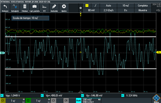
    At another test, we've connected one input to the output of the monitor, as shown in the diagram below. We've measured at the bnc cable before connecting it (green signal), and after then, we've measured the difference input after the AC coupling capacitors (blue signal).

      Vmax ~= 1200mV, Vmin ~= -1200mV -> Vpp ~= 2400mV

      Vmax ~= 200mV, Vmin ~= -200mV -> Vpp ~= 400mV

    Are so low levels of Vpp normal for SD SDI signals?

    Thank you in advance.

    Best regards,

    Tomás.

  • Hi Tomás,

    SMPTE specifies 800mVpp as the VOD on 75 ohm coaxial cable for SDI.

    There is a large difference between the voltage at R47 and R48 and the SDO-1-P and SDO-1-N sections.  Notice that the diode is not a part of the recommended device schematic. Have you tried removing the diode to see if you get an improved performance?

    Best,

    Nick


  • Hi Nick,

    We've removed the diode and we're getting now good standard SDI signal, so that's a great improvement. The board is decently transmitting the HD signal, and already with 3G errors appear in the image display.

    I'll upload some scopes next week so you can see the improvement. And then I will close the question, because PCB has many layout issues and I think those are the cause of 3G errors. 

    Thank you very much, Nick.

    Kind Regards, 

    Tomás.

  • Hi again,

    Here you have pictures of the different signals. All of them are HD 1080i and all they correspond to a pattern of colores bars.

    This first one is measured after reclocking:

      Vmax ~= 400mV, Vmin ~= -400 mV -> Vpp ~= 800mV

    And this next one is just on the single output (not differential):

      Vmax ~= 400mV, Vmin ~= -400 mV -> Vpp ~= 800mV

    Sorry for the quality, but I don't know what to do to improve the upload.

    Thank you and kind regards.

    Tomás