This thread has been locked.

If you have a related question, please click the "Ask a related question" button in the top right corner. The newly created question will be automatically linked to this question.

TI RS485 Transceivers (SNx5HVD08 and SN65HVD17xx) Not Working

Other Parts Discussed in Thread: SN65HVD08, SN65HVD1780

We have a RS485 design that works with 5V systems, but we need one that will operate with 3.3V systems as well.

We're trying to migrate our design from the MAX485CSA+ (which only runs on 5V) to one of the TI RS485 chips. We have been working with the SN65HVD08 and SN65HVD17XX parts.  However, we can't get any of the TI parts to work.  We've spent a lot of time trying different things, but we haven't been able to figure it out.  I need your help.

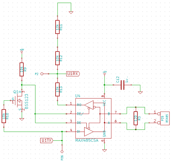
Below is a schematic of our circuit.  The RS485 works with the MAX485CSA part.  However, none of the TI parts work: specifically the microcontroller UART receiver doesn't get message from the RS485 bus and the RS485 bus doesn't get messages from the microcontroller UART transmitter.  The resistors on the output of the RS485 translator are to shift the 5 volt output of the MAX485CSA to 3.3 volts for our microcontroller.

An oscilloscope probe shows that the TI part is getting a good signal on pin 4 (the transmit pin) with input high voltages of 3.4 volts, which is above the Vih of 2.25 and 2.0 volts for the TI chips.

Pin 1, the receiving pin, is locked at 3.6 volts and doesn't move under any condition.

The TI chip's output on pin A and B are the same with voltage levels of 5.4 volts with a waveform that is the inverse of signal on the transmit pin (pin 4).

Any suggestions?  Thanks so much for your time!

  • Hi Chris,

    Can you help me to understand the circuitry controlling the RE/ and DE pins? It seems like when trying to transmit a '1' the FET would turn on, causing the enable pins to go low (disabling the driver). I believe you would want a separate pin from the uC controlling the enable pins. 

    Let me know,
    Jason Blackman 

  • Sure.  The UART transmit is a '1' when idle.  The FET gate is biased in this condition and DE goes low and /RE goes high, so the transmitter becomes disabled and the receiver becomes enabled.  So logically you can think of it as, "when you're not transmitting, you're receiving."

    However, I see what you're saying: the output is being told to go hi impedance and not actively driven to a '1' during transmits. 

    Maybe that's it.  I'll try your suggestion.  Thanks for your reply, and I'll report back.

  • Chris, your circuit actively drives Low. You can transmit a High passively by applying a pull-up resistor to the A-terminal and a pull-down to the B-terminal.

    for the receiver output connect a schottky diode (BAS81 or similar) in reverse between R and the controller input (I/O). So onnect Cathode with receiver output R, and the anode with the controller input. Then connect a 10k pull-up from the anode (or controller input) to the 3V controller supply. Thus when the receiver output (R) goes low, the schottky is forward biased and the controller I/O sees a low (or the VF of the diode). When the receiver output goes high, the diode is reverse biased and blocks. Then your pull-up prvides a high to the controller I/O.

    Hope this helps. Thomas


  • Well, quite frustrating...

    We ordered samples of the SN65HVD08 and SN65HVD1780 RS485 transceivers from ti.com for our testing and prototyping on this.  The parts arrived and the packaging was labeled as what we ordered.  However, the markings on the chips in the SN65HVD08 lot reveal that they are actually LDO 5V regulators!

    When we put the LDO in our circuit, it destroyed our prototype boards.  Thinking the cause of malfunction was the RS485 transceiver, we replaced it with a HVD1780 but it appeared not to work because the rest of the board was already destroyed from the encounter with the LDO...

    Having had a new board built up with a new SN65HVD1780, things are working.  Sigh.

    Thanks for your time on this.