This thread has been locked.

If you have a related question, please click the "Ask a related question" button in the top right corner. The newly created question will be automatically linked to this question.

SN65HVD24 doesn't receive properly when signals swapped

Other Parts Discussed in Thread: SN65HVD24, TXB0101

I submitted a techsupt request and was told instead to post here.  That'd better mean that TI reps actually answer *here* if they don't answer directly...

I have a product under development that needs to find the right RS-485 transceiver.  The original attempt was the MAX13451, but that either put too much load on the bus or doesn't drive strong enough, resulting in sagging and ringing on every transition and a very restrictive limit of how many units could be on the bus.

The SN65HVD24 was looking better until I hooked up the bus backwards (an absolute requirement of the design).  The receive output went from perfectly clean and viable to quite shredded, even though the A and B signals were just swapped.

Some background: the units connect to the bus for both inductively-coupled power and capacitively-coupled data.  The bus has 36V DC plus the RS-485 signal.  The SN65HVD24 is run from 5.5V and interfaces to a 3.3V microcontroller with a series resistor on the receive line.

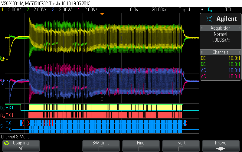
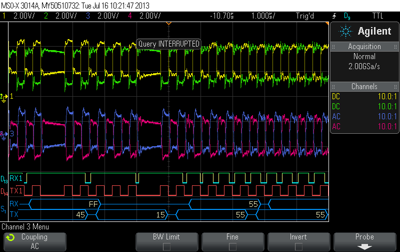
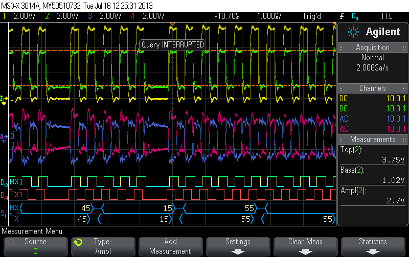
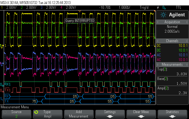
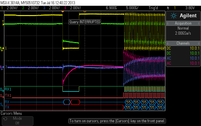
In the attached image are 3 tests.  The top shows a viable packet being sent, with yellow and green being probed between the capacitive coupling and the HVD24 (DC coupled probes, ground to the test board, signal clearly centered at 5.5v/2), while the digital signal is an isolated (ADuM, part of my test/program fixture) copy of the received signal output by the HVD24 through the series resistor into the microcontroller.  The middle image shows what happens when I reverse the A and B lines.  Instead of a viable receive signal it gets completely lost during the preamble and is almost never comprehensible after that.

The preamble (left of T0) is:

0x55 (x5) [condition/center bus]

0x44 0x11 0x45 0x15 (x5) [resync UART receive statemachine]

0x55 (x5) [recenter]

The bottom shot shows what happens when I double the preamble all the way around.  The signal still gets lost immediately in the resync section,but comes back in time for the data packet.  This results in a slightly higher successful reception rate (maybe 20% instead of 10%).

My understanding of RS-485 is that this should absolutely not be happening.  The input signal is clearly within range (they idle at the same voltage, halfway up VCC), so swapping the signals should have no effect other than inverting the output.

I have tried several chips and gotten the same result, though I can work through a few more if there's any chance that particular chips are bad.  As it stands though, I just sent out for boards to hold the MAX3292, which may be a better fit anyway because of the transmit pre-emphasis.

  • Hi Erik,

    I took two EVM's and had one send data to the other so we could watch the HVD24 receiver. Here are the scope shots of normal and reversed bus wiring, with the receiver output of the HVD24 shown below.

    Normal wiring

    Reversed wiring

    It shows the behavior you expect, where reversing the bus wires simply inverts the receiver output. 

    There must be something about your setup that I'm not understanding. If you could share a schematic, that would be helpful, as well as a scope shot that is zoomed in on a section where the receiver isn't toggling but the bus is. It's hard to tell exactly what is happening on the bus because it's zoomed way out to show an entire packet. 

    Also, I wasn't sure what you meant about inductively coupled power and capacitively coupled data. Are you saying the RS-485 bus signals are riding on top of +36V? Or that there is a separate wire for power and the bus lines? Again, a schematic would help us figure out what your system looks like. 

    Thanks!
    Jason Blackman 

  • I've attached a PDF of a overview schematic of the system.  Special note: the main bus is not twisted pair, it's "lamp cord" as per fundamental product requirement.  There are roughly 5 meters of it on my desk right now, with test units at either end.

    Probe connections are noted in bold purple.

    Here's an overview of a normal transmission, and closeup:

    And here's with the bus reversed at the blue 'x' in the schematic:

    Note that channels 1 and 2 simply swap when the bus is inverted, but serial receive is trashed (ignoring the scope serial decoder's inability to invert the RX line for me, it's still bogus).

    overview.pdf
  • Hi Erik,

    Can you probe the R output of the HVD24 with an analog channel? I want to see if the R output is trying to toggle and can't get all the way to the ADuM thresholds, or whether it isn't trying.  

    Thanks!
    Jason Blackman 

  • I'll get that rigged up here in a sec (need to solder a test wire in the middle of the board stack), but here's another test that's instructive:

    *Software* invert the TX line as coming from the microcontroller, which should do nothing but result in an inverted signal on the far side, and I get the same results.  That "eliminates" the possible interactions between which of A or B is 36VDC vs ground.

    What I've noticed over the development of this product however, is that the exact timing between asserting DE and starting to transmit data seems to have a lot to do with how the receiver copes. However, the signal (probes 1 and 2) is about as clean as I've ever seen in either case, so that doesn't seem to be the issue.  However, I can play with those timings because they're adjustable not only in software but in realtime.

  • Hi Erik,

    Still looking at the schematic and had another thought. Are the two bus lines that L1 and L2 connect to +36V and GND? If so, is the power portion of the circuit still working when the cross wiring occurs? I would check to make sure Vcc on the HVD24 is valid.

    Thanks,
    Jason Blackman 

  • Sorry, yeah, forgot to include the bridge rectifier before the power supply in that schematic.

  • Here's a shot of a normal transmit with 1 (yellow) probing the R pin of the HVD24, and 2 (green) probing the other side of the resistor (1K) that feeds the microcontroller and the ADuM (which drives D13).

    And then software inverted transmit:

    Interestingly, while the R probe just looks inverted, after the resistor is very different, depending on the signal orientation...

    The original plan was to use a TXB0101 to translate R down to 3.3V but that failed miserably for reasons I don't at this point understand.  Thus for now I've just put a series resistor in place.  I guess the next test would be to drop the resistance and see what happens.  Just worried about overloading the ATXmega input pin...

  • Switched in a 470R resistor for the 1K and it receives properly now, with the amplitude up to 3.1V.  Still not sure why it's not the same as non-inverted, which is now 3.3V.  It looks like the DE sequence actually "sets" the functional range at the beginning of the packet:

    Normal:

    Soft invert:

    Guess I've got more to learn about digital input buffers....

  • Glad you've at least got it working. I'm not sure why the amplitude changes with the cross-wiring either. 

    Let me know if you have any more trouble!

    Thanks,
    Jason Blackman