This thread has been locked.

If you have a related question, please click the "Ask a related question" button in the top right corner. The newly created question will be automatically linked to this question.

ISO1176T for RS485/Modbus? (circuit correct?)

Other Parts Discussed in Thread: PROFIBUS, ISO1176T, ISO1050

Hi,


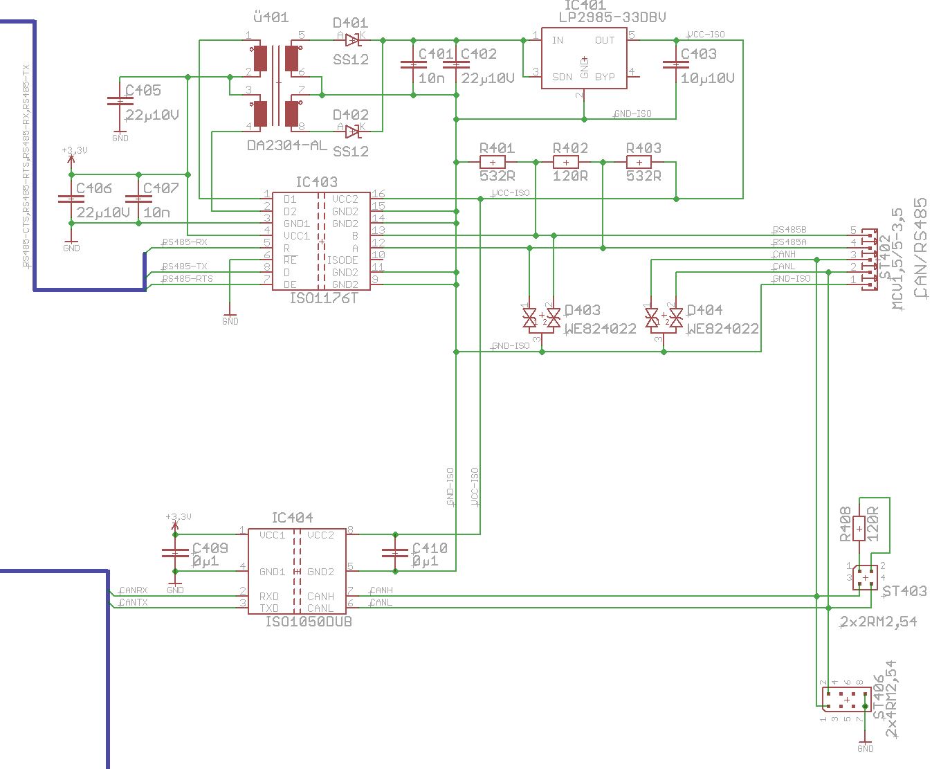
can I use the 1176T for Modbus-RTU ? I need some ESD protection as well so I added TVS diodes.
Could somone please review my RS485 circuit?

Is the resistor value of R401 & R403 correct? I know that profibus requires 220R but a value of 390~600R should be ok for Modbus / RS485?

Is the CAN circuit good too ?

My Bus Settings are:

1) 115kbaud

2) max. 32 Slaves (typical 4-8)

3) cable 50 meter length

4) Shielded twisted pair

Kind regards


E.G.

  • Hi Ersan,

    A couple of things:

    • Consider placing a 1kohm resistor from /RE to GND to limit any potential noise currents
    • It looks like your LDO (IC401) may be a 3.3V regulator ( "-33DBV" ).  Note that VCC2 for the ISO1176T is specified between 4.75V and 5.25V.  If it is indeed a 5V regulator, disregard this comment.
    • R401 and R403 seem reasonable.  I might recommend making them a bit larger, as the ISO1176T has internal open, short, and idle failsafe, so external pull-up/down resistors are primarily adding additional noise margin.  For 4 or 8 receivers, 532ohm should be fine, but as you increase to your maximum of 32 receivers or beyond, increasing R401 and R403 will alleviate your common mode bus loading, while still providing adequate noise margin.  For complete analysis of failsafe levels vs common mode loading, check out these two application notes.

    For the ISO1050 portion, I'll defer to an apps engineer who is better versed on that device.

  • Hi Bart,

    thank you for the Informations.

    - The LDO is a 5V regulator (wrong value on Item). 

    - I added a RE series resistor

    - R401 + R403  , for up to 32 nodes, 1k would be better due the equ. in the PDF?

    Kind regards

    Ersan

  • Hi Ersan,

    I reviewing the CAN portion of the schematic, what is ST406 and ST403? Are they connectors or bus protection?

    I general I would recommend placing bus capactiors to GND2 on CANH and CANL (typically these values are 68-100pF), and bus protection diodes to GND2 as well. The NUP2105 is a single device that protects both CANH and CANL bi-directionally, and the MMBZ27 are bi-directional protection devices for 1 bus line each (so a total of 2 will be needed).

    Please let me know if you have any questions,

    John

  • Hi John,

    thank you for your reply. ST406 & ST403 are phoenix contact connectors.

    I added a 100pF cap to CANH & CANL to GND2.


    Kind regards,

    Ersan

  • Hi Ersan,

    In addition, I would recommend placing external protection diodes on both CANH and CANL as well. These will make the system more robust to transients and ESD that can occur on the bus pins.

    Thanks,

    John

  • Ersan,

    For R401 & R403 = 1kohm, you have a failsafe voltage of +30mV.  Given VIT(+) of -10mV for the ISO1176T, this gives you 40mVpeak-to-peak of noise margin.  Whether this is acceptable will depend on the noise you expect to encounter in your operating environment.  There will always be a tradeoff between noise margin and common-mode bus loading when choosing failsafe resistor values.