This thread has been locked.

If you have a related question, please click the "Ask a related question" button in the top right corner. The newly created question will be automatically linked to this question.

Proper isolated RS485 end nodes termination for high common mode conducted noise immunity

Other Parts Discussed in Thread: SN75176B

Hello experts,

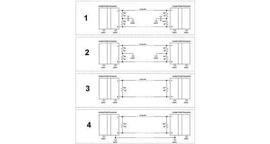
I want to know the right way to terminate two isolated RS485 end nodes for high common mode conducted noise (150K-100MHz) immunity. I am using SN75176B with a couple of opto-couplers and isolated power module to implement the isolated RS485 transceiver.

I figured out four possible schemes. There might be more. Could you help to point out the right one and explain why?

Thanks in advance.

  • I recommend No.3.

    because your are using isolation, the common-mode from the driver output is only the driver's output offset voltage, Vos which is around Vcc/2. The other common-mode contributions due to ground shifts between driver and remote receiver are eliminated by isolation.

    Make sure you use twisted pair cable. This is your best defense against common-mode noise from external noise sources. Using non-twisted cable, such as flat-band wire or lamp wire, converts common-mode noise into differential noise which your receiver will not be able to reject.

    If you have a specific noise frequency range in mind you want to protect against, you might use common-mode chokes in you data lines.

    regards, Thomas

  • Hello Thomas,

    Thanks for the reply.

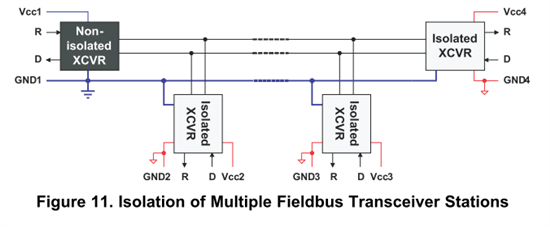
    However, I found your recommendation is conflict with the view shown in app note slla272b figure 11 (see below) where all isolated nodes reference grounds (the blue line) are connected together through a separate line. This corresponds to No.4.

    In No.3, what would you expect the voltage difference between GND2 and GND3? If this voltage may vary from application to application, could the enormous voltage difference caused by static charges lead to any damage to the transceivers? No.2 and No.4 are trying to eliminate such voltage difference uncertainty.

    Could you shed more light on this topic? Thanks.

  • I'm sorry for having not seen your question earlier.

    The design above is known as single-point reference design. It avoids difference between isolated grounds but requires an additional wire. If you don't mind the expense, of course this is a great solution.

    if you don't use a separate ground wire, the difference between GND2 and GND3 the voltage will be also zero IF you use transceivers with equal supply levels.

    If you use a 5V transceiver on node 2 and a 3.3V transceiver at node 3, you will measure the common-mode difference between GND2 and GND3. The common-mode output is typically Vcc/2. So for the 5V transceiver you have 2.5V and for the 3.3V transceiver you have 1.65V as common-mode levels. The difference of 850mV you would measure between GND2 and GND3.

    regards, Thomas