Because of the Thanksgiving holiday in the U.S., TI E2E™ design support forum responses may be delayed from November 25 through December 2. Thank you for your patience.

This thread has been locked.

If you have a related question, please click the "Ask a related question" button in the top right corner. The newly created question will be automatically linked to this question.

TPD6E001 Ground Pin Connection

Other Parts Discussed in Thread: TPD6E001

Hi,there
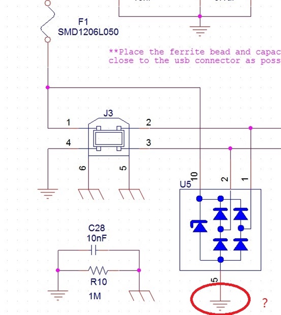
i am designing a USB based project.i choose the TPD6E001 as the ESD protection device,i have two questions that need your help. i've uploaded the USB part of my schematic for illustration.
1.As indicated,two ground symbols,the usb shield ground and the signal ground,exist in the system,so which of
the two grounds should the common ground of ESD device be connected to?i connect to the signal ground,but i'am
not sure whether it will work.

2.i google on how to bridge shield ground and signal ground and two different solutions are found:
(1)Place a large resistor(usually 1M ohm) paralleled with a capacitor between the two grounds.
(2)Isolate the two grounds with a 0ohm resistor or a ferrite bead.
Can someone explain the two solutions in detail, in which situation they are applicable?


Thanks for your attention!

Sincerely,

Adam

  • Adam,

    Here are the answers to your questions:

    1) Use shield ground for the TPD6E001, any inductance in the return path to earth ground will cause large voltages due to the sharp di/dt involved with ESD.

    2) Honestly, there is no simple answer to the best approach in interconnecting signal and chassis grounds. The entire system has to be considered, how noisy is the digital logic vs. how sensitive is the analog logic. I suggest an excellent article at TI within which you should be able to find these answers:

    http://www.ti.com/lit/an/szza009/szza009.pdf

    Regards,