Because of the Thanksgiving holiday in the U.S., TI E2E™ design support forum responses may be delayed from November 25 through December 2. Thank you for your patience.

This thread has been locked.

If you have a related question, please click the "Ask a related question" button in the top right corner. The newly created question will be automatically linked to this question.

SN65LVCP22 LVDS Repeater questions

Other Parts Discussed in Thread: SN65LVCP22

Hello,
I would like to have further explanations about SN65LVCP22 2x2 LVDS CrossPoints.

The part will be used in a 2:1 mux architecture.

1. Clarification on the differences between bit rate and frequency

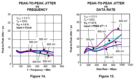
I have seen in the datasheet several charts that depict both the peak-to-peak jitter evolution in function of the frequency and the peak-to-peak jitter evolution depending on the bit rate. Having read those charts I do not understand why the peak-to-peak jitter value given a frequency is different from the peak-to-peak jitter value read for the equivalent bit rate at equal conditions.

What I mean by "equivalent bit rate" is for example a signal at a bitrate of 1000Mbps has its fundamental frequency at 500MHz (is it correct?). Then, continuing with both 500MHz and 1000Mbps values, and reading the peak-to-peak jitter values on the two charts below (referenced as Figures 14 and 15 in the datasheet), for 800mV curb the peak-to-peak jitter is 7ps@500MHz on the Figure 14 and 40ps@1000Mbps on the Figure 15.

Thus my question is: why are the two values different each other while I thought they would be equal?

Did I miss something and what?

The question is applicable to both the charts and the table extracted from the SN65LVCP22 datasheet shown below.

Finally, what value should I take to calculate total jitter?

2.Total jitter calculation

How should I deal with peak-to-peak and random jitter values in order to evaluate a jitter budget?
 I have read in literature that:  Total_Jitter = Deterministic_Jitter + 2*N*Random_Jitter where N is a factor depending on the BER we would like to reach.

For example:

 (1) BER = 1e-16 --> N=8,222 --> TJmax@1000Mbps = 105 + 8,222*1,8 = 120ps

However, the last time I used a LVDS buffer/reapeater similar to the SN65LVCP22, it has been said to me that as the repeater does not lock to any PLL the Total_Jitter has to be simply Deterministic_Jitter + Random_Jitter (without the factor 2*N).

For example:

(2) TJ =105 + 1,8 = 106,8ps

Thus, what is the good calculation (1 or 2 or other) for the SN65LVCP22?

3. Pulse skew

It has also been said to me that pulse skew do not have to be added to DJ and RJ to calculate the budget jitter. However I do not understand why.

I know what is Pulse Skew (that is time difference between Low-to-High and High-to-Low Delay) thus I would think that it has an influence on jitter. But as written above, it has been said to me that pulse skew as no influence on jitter...

I would be really grateful if anyone could explain me if and why Pulse Skew does not need to be added when calculating either the budget jitter or the receiver skew margin.

4. Relation between input and output jitters

Does the SN65LVCP22 do data recovery? As it is only a repeater/buffer I would say it does not.

If it does not do recovery of the data, then: does the output jitter equal jitter received to the input + total jitter that the SN65LVCP induces ?
Let's have an example: assuming an input jitter of 180ps (whatever the frequency or the bitrate of the signal received), the SN65LVCP22 adds the jitter calculated in 2 - example (1) that is 120ps, then the total output jitter is 180 + 120 = 300ps.

Is it the good way for calculating the jitter to the output?

Thank for responding

Julien Appaix

  • Hi Julien,


    Thank you for your very insightful questions!

    1. You are correct in assuming that figures 14 and 15 share the same fundamental frequency but if you notice in figures 14 and 15 the input to the device is different. Figure 14 shows the the additive jitter from a clock pattern while figure 15 shows the additive jitter from a PRBS23 data pattern. There will be little to no jitter present on the clock pattern (mostly Duty Cycle Distortion - DCD) while the PRBS23 data pattern will contain data dependent jitter (DDJ) and other ISI effects. Clock patterns are typically used when measuring RMS jitter since there is little to no DJ (ISI) present on a clock. The jitter numbers in Figure 15 would change with the type of data pattern that was used. For example if PRBS31 was used for the test I would expect that the number would rise and if PRBS7 was used I would expect that number to fall. To answer you second question from one I would take the number that best represent your application. If you are using the MUX to distribute a clock then figure 14 is relevant but if you are distributing data than figure 15 would be more accurate although the number would most likely change depending on the run length of your data.

    2. There is a lot of different literature out there on jitter as this is a very complex topic. The two equations you referenced though are one in the same, the difference is the units that RJ is being talked about in.

         Rj(pk-pk) = 2NRj(RMS);

    You multiply by 2 since this is a Gaussian distribution and N represents the BER you are trying to achieve. For a BER of 10^-12 N is ~14. For more information on these topics you can visit Agilent or Teks website as they typically have good papers that go into a lot of detail. For an overview of jitter check out my blog posts on Jitter and Measuring Jitter on the Analog Wire: Get Connected

    3. Pulse skew will contribute to the overall jitter budget as the 50% crossing can change causing some horizontal eye closure.

    4. No the SN65LVCP22 does not have any CDR functionality. You are correct that the output jitter would be equal to the input jitter plus the additive jitter of the SN65LVCP22.

  • Hello Michael,


    First of all I would like to thank you for responding so fast.

    Regarding your responses:

    1. Fully understood, it is crystal clear now.

    2. I will be grateful if you would spend more time on this question. I am not sure that the two equations I referenced through are "one in the same" due another expert said to me that total jitter induced by a repeater should be calculated adding both RJ(RMS) and DJ(pk-pk) without involving any N factor. He argued that it should be done so due to "repeaters do not have PLL to lock to". Personnally I cannot understand what it means, can you?

    However, I know all the aspects you referenced through (I mean differences between pk-pk and RMS RJs and so on). The point I cannot get actually concerns the fact that "no PLL" would mean "no N factor" (according to my second expert contact)...

    3. Do you know any literature that may support your responses? Could you type an example with values please?

    4. Ok, great !

    Finally, if you do know any literature that may support your responses (and increase my knowledge by the way ;-)), do not hesitate to set links as you did in your previous reply.


    Best regards,

    Julien APPAIX


  • Hello Michael,

    I really appreciated your reply to my first post.

    However it seems that nobody responded to the second one.


    Please, may someone respond ??


    BR,

    Julien Appaix 

  • Hi Julian,

    I apologize for my delay in response to your question.

    2.Total jitter calculation

    [Julian]

    How should I deal with peak-to-peak and random jitter values in order to evaluate a jitter budget?
     I have read in literature that:  Total_Jitter = Deterministic_Jitter + 2*N*Random_Jitter where N is a factor depending on the BER we would like to reach.

    For example:

     (1) BER = 1e-16 --> N=8,222 --> TJmax@1000Mbps = 105 + 8,222*1,8 = 120ps

    However, the last time I used a LVDS buffer/reapeater similar to the SN65LVCP22, it has been said to me that as the repeater does not lock to any PLL the Total_Jitter has to be simply Deterministic_Jitter + Random_Jitter (without the factor 2*N).

    For example:

    (2) TJ =105 + 1,8 = 106,8ps

    Thus, what is the good calculation (1 or 2 or other) for the SN65LVCP22?

    [Mike]

    2. There is a lot of different literature out there on jitter as this is a very complex topic. The two equations you referenced though are one in the same, the difference is the units that RJ is being talked about in.

         Rj(pk-pk) = 2NRj(RMS);

    You multiply by 2 since this is a Gaussian distribution and N represents the BER you are trying to achieve. For a BER of 10^-12 N is ~14. For more information on these topics you can visit Agilent or Teks website as they typically have good papers that go into a lot of detail. For an overview of jitter check out my blog posts on Jitter and Measuring Jitter on the Analog Wire: Get Connected

    [Julian]

    2. I will be grateful if you would spend more time on this question. I am not sure that the two equations I referenced through are "one in the same" due another expert said to me that total jitter induced by a repeater should be calculated adding both RJ(RMS) and DJ(pk-pk) without involving any N factor. He argued that it should be done so due to "repeaters do not have PLL to lock to". Personnally I cannot understand what it means, can you?

    However, I know all the aspects you referenced through (I mean differences between pk-pk and RMS RJs and so on). The point I cannot get actually concerns the fact that "no PLL" would mean "no N factor" (according to my second expert contact).

    [Mike]

    I believe that TJ should be calculated for the situation and has little or nothing to do with whether a device has a PLL or not. The purpose behind a PLL is remove excess jitter from an incoming clock stream by phase locking the clock to a local reference oscillator there by removing the jitter that is present within that clock. The "jitter cleaned" clock on the other side of the PLL will now possess the jitter characteristics of the local oscillator used to run the PLL. A CDR posses a PLL as well and is used to jitter clean incoming data and not a clock. If the incoming data possess enough transition density the CDR will recover a clock from the data and feed that to a local PLL which will then be used to re-clock the data back out with lower jitter. Of course in both of the methods described all of the jitter cannot be removed but if done properly it should be significantly less than what you started with.

    A repeater is going to remove jitter as well but it does not work the same as the aforementioned methods. A repeater, if it possess capabilities of equalization and/or de/pre-emphasis simply removes the effects of ISI due to channel impairments. A repeater does not remove the effects of RJ at any level, it will simply add the intrinsic RJ present in the device. This is why the jitter that comes from a repeater can be thought of as additive.

    In my opinion you should think of the link as a single entity and try to meet a jitter budget for that link. Since you are already familiar with the peak to peak and RMS concepts that we discussed in our previous post you should be able to calculate this relatively easily with the understanding that a clock does not suffer from the effects of ISI and that the relationship between the two different equations is:

    RJ(pk-pk) = 2NRJ(RMS);

    TJ = DJ + Rjpk-pk

    3. Here is some information that you can look over:

             a. http://www.ti.com/lit/an/slyt179/slyt179.pdf

             b. http://www.ti.com/lit/an/scaa055/scaa055.pdf

    Jitter is defined as any deviation in an clock or data edge form its ideal position. If a device suffers from some level of pulse skew it is going to add to the amount of DJ as the ideal edge is moving around.


    I hope this helps!

  • Hi Julien,


    I was doing some surfing today and came across this document:http://www.ti.com/lit/ml/snaa103/snaa103.pdf


    This is a great document that was put out by NSC in 2006.