This thread has been locked.

If you have a related question, please click the "Ask a related question" button in the top right corner. The newly created question will be automatically linked to this question.

DS125BR820 and TLK1102E Difference

Other Parts Discussed in Thread: DS125BR820, TLK1102E, DS100BR111, DS125BR111, DS80PCI810, DS110DF111, DS110DF410

Hello,

I have some questions:

1) what is the difference in structure between DS125BR820 and TLK1102E, one is categorized as repeater and the other as equalizer? (can they be used interchangeably?)

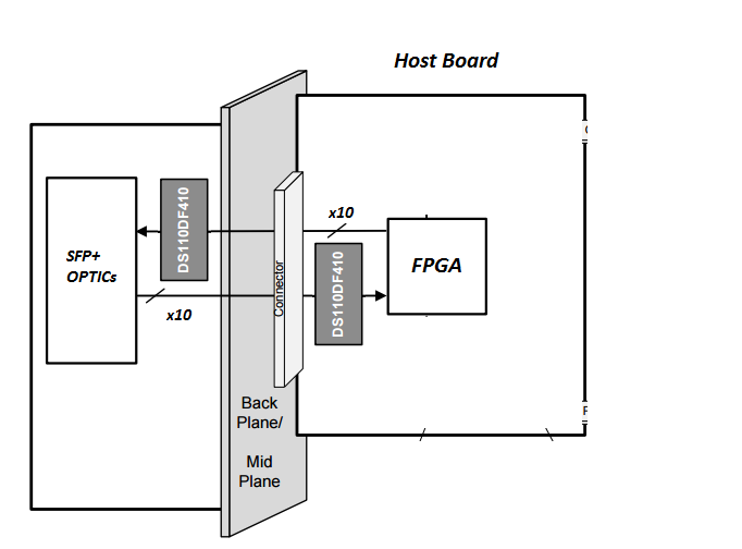
2) In our customer application we have this situation:

main FPGA ---- about 10" FR4 --- Molex Connector ---- about 5" FR4 --- SFP+ Optics

which one of these parts is best fit?

  • Hi Morsu,

    The TLK1102E is a linear equalizer followed by a limiting amplifier. This device has much in common with the DS100BR111.

    The DS125BR820 is linear from input to output.  The BR820 and similar devices like the DS125BR111 and DS80PCI810 are generally preferred when any type of link or equalization training will be used on the serial link.  The linear operation preserves the Tx FIR analog characteristics allowing the far-end receiver to correctly guide the training process to robust equalization solution.

    For most SFP+ applications the DS110DF111 retimer is used to ensure a very clean eye at the host interface.  With just an equalizer like the DS100BR111 or the TLK1102E any transmit Dj from the FPGA output cannot be filtered out and will be passed onto the SFP+ host interface.

    If multiple SFP+ interfaces are used, the DS110DF410 may be the best option.

    Regards,

    Lee

  • Hi Lee,
    Thanks for the reply.
    I have only one more question:
    As you noticed if we use DS110DF410 in our customer application in FPGA receiver side (Host Board), and instead of using SFP+ we use CFP optics (optic card), do this cause any problem like CFP's REFCLK incompatibility or ...?
    (consider optics as a separate card connected to Molex connector with another DS110DF410 in its receiver side, each card has 10 lines of 10.3-11.2G signals)

    (main FPGA --- DF410 ---- about 10" FR4 --- ) Molex [Host Board]
    Molex (---- FR4 --- DF410 --- Optics)[Optic Card]

    Thanks again
    Regards,
    Morsu
  • Morsu,

    Cascading DS110DF410 devices is not an issue.  The CFP REFCLK signal is based on the optical rate, unlike the DS110DF410 REFCLK input which requires a constant 25 MHz.  The host system would have to generate the optical REFCLK for CFP separately from the 25 MHz clock required for the DS110DF410.

    Regards,

    Lee

  • Hi Lee,

    In fact my question was not clear.

    Please find these pictures below, explain my question in better details:

    In fact my question was that DF410 line delay may cause some incompatibility (skew) with CFP REFCLK. am I wrong?

    regards,

    Morsu

  • Morsu,

    I have read through the reference clock section in the CFP MSA.  The key paragraph is copied below.

    The REFCLK shall be CML differential AC coupled and terminated within the CFP module as shown in Figure 4-1: High Speed I/O for Data and Clocks. There is no required phase relationship between the data lanes and the reference clock, but the clock frequency shall not deviate more than specified in Table 4-2. For detailed clock characteristics please refer to the below table.

    The DS110DF410 will impact the phase relationship between the CFP REFCLK and the data.  It has an internal delay of just over 1.5 Unit Intervals of the data, but since the specification does not limit the phase it should be okay.

    Regards,

    Lee

  • Thanks Lee,
    I hope you have a great day.
    regards,
    Morsu.