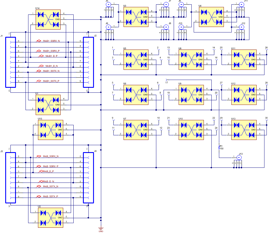
The schematic for the TPD4E110DP Eval board is not legible. I can't see the reference designators. Could someone help get a better schematic?

-
Ask a related question
What is a related question?A related question is a question created from another question. When the related question is created, it will be automatically linked to the original question.