This thread has been locked.

If you have a related question, please click the "Ask a related question" button in the top right corner. The newly created question will be automatically linked to this question.

TIR1000: TIR1000 Decoder function not working

Part Number: TIR1000

The decoder function on the TIR1000 chip isn't working for us. When we send a signal (to IR_RXD) we don't get anything out on U_RXD (the output stays constant at 3.3 V), based on oscilloscope testing. We have tried resetting and we have tried three different chips and have gotten the same result on all of them. Here are our connections:

VCC: 3.3 V
GND: to ground on USB/uart adapter
CLK: 1.843 MHz sine wave from a function generator
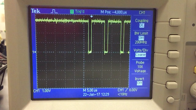
IR_RXD: +3.3 V pulses, about 1.6 microseconds wide, verified on oscilloscope. (we are getting this from the IR_TXD pin on a separate TIR1000 chip. Ultimately this pin will be connected to a photodiode, but we are testing the boards directly together first to verify that they are working as expected).

We can't figure out why no signal is produced on U_RXD.  What are we missing?

  • Hi Jennifer,

    Is it possible for you to invert the signal that you are providing to the IR_RXD input? The encoder of the TIR1000 creates ~1.6 us high pulses on IR_TXD when a low bit is present at the U_TXD input. The decoder function looks for low pulses on IR_RXD rather than high pulses, though - see Figure 5 in the datasheet for an example. This inversion would occur naturally with most optoelectronics, but if you are directly connecting IR_TXD to IR_RXD you would need to do it manually.

    I hope helps - please let me know if the issue persists.

    Regards,
    Max
  • Oh, ok, thanks!  It does say in the datasheet that "The TIR1000 and TIR1000I devices can decode either negative or positive pulses on IR_RXD" (section 7.3).  But I will try inverting the signal and see.

    Jennifer

  • Jennifer,

    That's a good catch, and sorry for my mix-up. You're right that the device should support the opposite polarity as well, even though it is uncommon. If that does fix the issue, then, please be sure to let us know. If not, though, the next thing I'd recommend checking is the clock signal. You mentioned using a sine wave, but typically this input is intended to take a full logic-level square wave signal (e.g., from a UART's clock output). Could you reconfigure your function generator to output a square wave instead?

    Max
  • We inverted the signal using a digital inverter, and we also changed the function generator to produce a square wave.  Unfortunately, we are still not getting any signal on U_RXD.  The output on U_RXD is constant at 3.3 V.  

    Here is the input signal to IR_RXD now:

  • Jennifer,

    That's strange - the input signal looks OK to me, so I'm not sure what could be going wrong. Can you please check a few other things?

    - Is RESET (pin 5) low?
    - Is the signal at 16XCLK (pin 1) a square wave (0 V to 3.3 V) at the right frequency?
    - Does the IR_TXD (pin 7) output signal look normal (right duration, voltages, etc.)?

    Is there a schematic or layout you could send me so that I could double-check the connections?

    Regards,
    Max
  • Got it!

    We needed to ground the RESET pin ... once we did that it worked great.

    Thanks for the help!!