This thread has been locked.

If you have a related question, please click the "Ask a related question" button in the top right corner. The newly created question will be automatically linked to this question.

TLK106L: ethernet communication not stable

Part Number: TLK106L
Other Parts Discussed in Thread: TLK106, DP83822I

In my design I use TLK106L in RMII connection.
I have a "not stable" behaviour during ping test between my board and the Personal Computer I use for test.
Please note that I used TLK106L in many designs without problem.
I executed a lot of test to find the problem and (finally) it seams the the TLK doesn't work properly. 

The clock source for TLK and MAC is designed as figure 6-2 of the data-sheet (SLLSEE3D –AUGUST 2013–REVISED APRIL 2016).

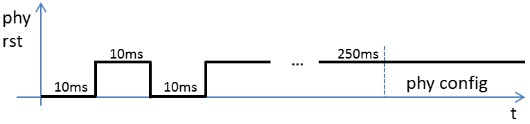
The question is related to timing constraint, paragraph 4.10.1 Power-Up Timing, specification t2: "XI Clock must be stable for minimum of 1 µs prior to VDD ramp."
In my design TLK, MAC and clock oscillator share the same supply, as consequence the T2 constraint is not met.

What could happen?

Thanks for your support, best regards.
Corrado

  • Hi Corrado,

    For device to functional reliably, timing constraint needs to be met at power up.
    When you see "not stable" behaviour : can you elaborate more on this : is link stable ?


    Regards,
    Geet
  • Dear Geet,

    the link is not stable, I see some percentage of ping lost. 

    Take in count that I have 30 boards with 2 ethenet ports each,  60 ports. About 30% of them have "not stable" behaviour.

    In attachment our technical analisys, please see the file, I hope it is clear to better understand the issue.

    Thanks

    regards

    Corrado000909_ISSUE_00_00.pdf

  • Hi,

    Went thru schematics and see you have inductors in series to AVDD3V3 and couple of other places.

    What's the reason you have introduced these ?
    What's value of these inductors ?

    Also per earlier post clock is not available at Power, as an experiment can you try providing clock before the POR on unstable boards and see if it improves ?

    Regards,
    Geet
  • Dear Geet,

    the inductor is a ferrite used to separate digital from analog rails. I normally use this solution.

    About the clock vs POR: we already did this experiment, but the result is again "link not stable", please see attached waveform.

    It is the "RMII_PHY_RST" signal driven by the FPGA logic: during this time the clock is stable.

    The reset is driven at '0' for 10msec, the PHY is configured after 250msec from reset rising edge

    Best regartds

    Corrado

  • Thanks for the clarification on ferrite bead. It ok.

    On Clock at POR, I was referrring to below where, clock shall be available before VDD ramp.

     4.10.1 Power-Up Timing, specification t2: "XI Clock must be stable for minimum of 1 µs prior to VDD ramp.

    Did you try this experiement as well ?

    Regards,

    Geet

  • Dear Geet,

    it is not possible to separate VDD pin, I can't generate a VDD ramp after clock signal.

    In the meantime, in one board, I used DP83822IRHBT in place of TLK106. It seems more stable (no error till now) but I have only one board modified...

    Besides, I have the TL106 samples: in your opinion can be useful to test these devices? Is it possible from your side?

    Thanks

    Best regards

    Corrado

  • Hi Corrado,

    Is the TLK106 does not have a stable clock for 1uS before ramp, you can see issues that you describe.
    I do not think it would be useful to receive the units because the application is already outside the device's requirements.
    You should not see this constrain in the DP83822I.

    Best regards,
    Ross
  • Dear Ross,
    thank you, so I'll replace TLK106L with DP83822I.
    With DP83822I no need to have clock signal before VDD ramp, am I right?
    In this way I hope to fix my problem.
    Regards

    Corrado
  • Hi Corrado,

    You are correct. You can provide the clock signal when you are ramping.

    Best regards,
    Ross