This thread has been locked.

If you have a related question, please click the "Ask a related question" button in the top right corner. The newly created question will be automatically linked to this question.

DS3695A: Does this transceiver need external biasing on the differential pair outputs?

Part Number: DS3695A

Please forgive me if this question is silly. I'm having difficulty finding this information on the DS3695A's data sheet. 

I need to know if this component needs external biasing on pins 6 and 7. Like what's pictured here:

If so, what values should the resistors be?

Is this a standard practice to RS485 transceivers?

  • Hi Daniel,

    thanks for reaching out, this is a good question. To determine if a passive fail safe resistor network is needed, a look at the differential Input threshold voltage of the receiver tells you if you need a external biasing.

    So lets take a look at the DSA3695A datasheet. At the section Electrical Characteristics on page 3 you'll find:

    VTH Differential Input Threshold Voltage for Receiver  −0.2 V to +0.2 V -> this means any voltage between -0.2 V to +0.2 V is undefined and a fail safe biasing is necessary like shown on your picture.

    If yo look a more modern device like the THVD15xx you can see in section 7.6 Electrical Characteristics in the datasheet Positive-going input threshold voltage is -20 mV and Negative-going input threshold voltage -200 mV so its always below 0 V which indicates that the device has a internal fail safe biasing.

    In order to design the passive fail safe resistor network for a 5 V RS-485 system you can go on with the values shown on your picture if you wan't to make it work quickly. For more details please take a look at this application note:

     /cfs-file/__key/communityserver-discussions-components-files/138/7127.7824.slyt324.pdf  

    Additional info also here:

    https://e2e.ti.com/support/interface/industrial_interface/w/industrial_interface/2575.the-unit-load-in-rs485?keyMatch=rs-485%20unit%20load&tisearch=Search-EN-Everything

    /cfs-file/__key/communityserver-discussions-components-files/138/8228.RS485Infographic.pdf

    Please let me know if that helps you out, don't hesitate to ask further questions!

    Kind regards 

    Dierk

  • Dierk,

    Thanks so much for your input. You made that very clear.

    However, adding the external basing didn't help the way I expected it to. I'm still having intermittent communication issues.

    Here's an example of what I'm trying to do:

    I'm trying to convert the output of the SN65HVD63 to RS485. Everything I'm reading says I'm doing it correctly but when I add the external biasing on the DS3695 communication fails. When I measure the differential pair it looks fine though. 

    Thanks again,

    Daniel


  • Hi Daniel,

    do you operate with an open loop like shown on your schematic, if yes maybe you have forgot about the other 120 Ohm termination resistor at the end of the Bus-Cable.

    If you have not connected (nodes) and a cable with 120 Ohm termination at the AB output, you have to change the 120 Ohm resistor between pin 7 and pin 6 to 60 Ohms. Other than that the schematic seems to be good.

    If this is nor solving your problems we have to check your signal wave-forms.

    Kind regards
    Dierk
  • Dierk,

    I'm not operating with an open loop. It's connected to another design using the same DS3695A via a small cable. But I see now that the other design does not have external biasing resistors populated. I believe it should. Is that correct?

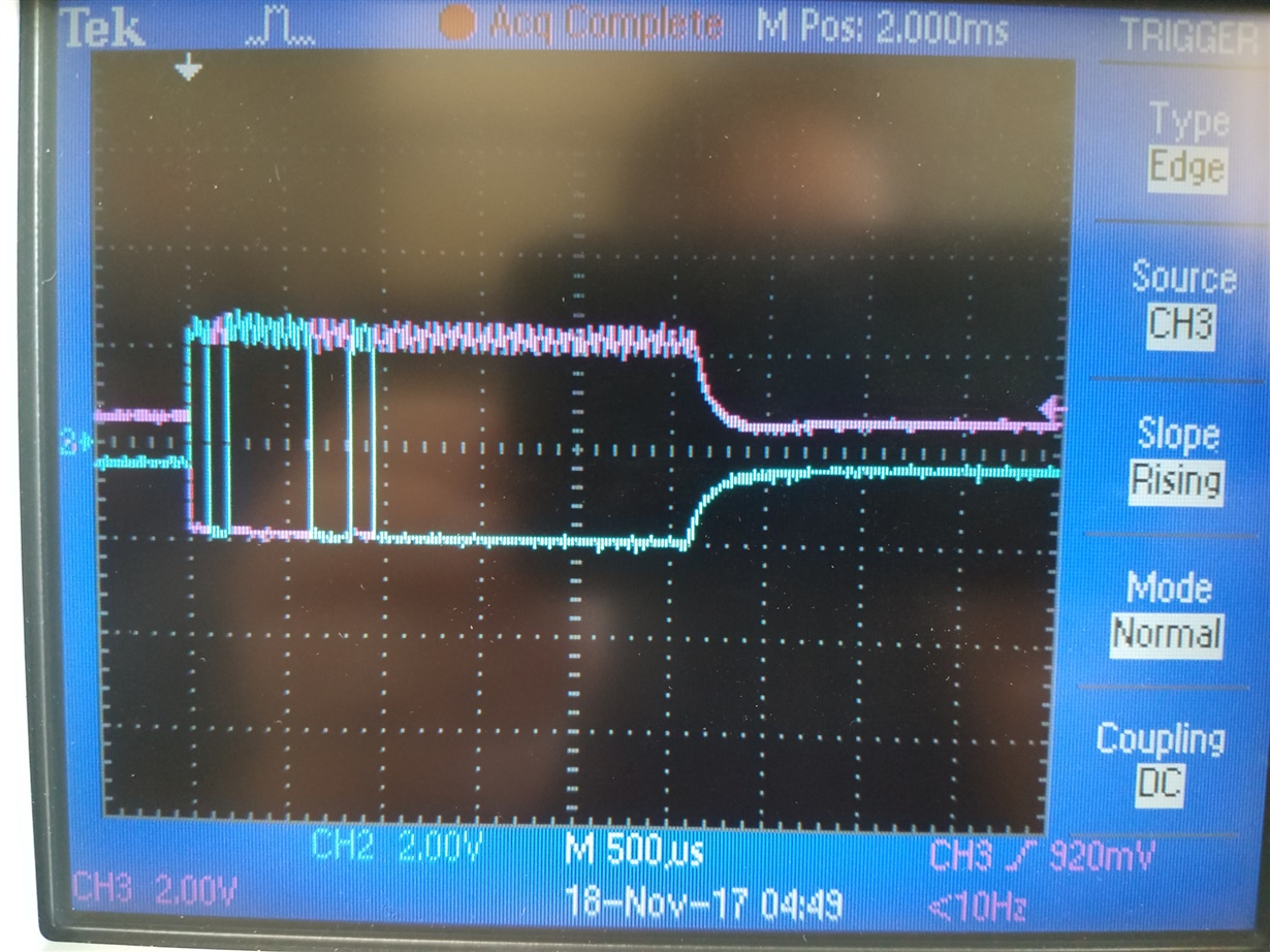
    However, I was taking measurements with an open loop. When transmitting without bias resistors populated I get the following differential pair:

    This is what made me believe I needed the biasing resistors in the first place. 

    However, when I populate the bias resistors I don't get a differential pair output. Looking at the logic side of the DS3695A I see the following before any attempt to send data:

    R0 - Low (0V)

    DI - High (5V)

    RE/DE - Low (0V)

    This tells me the DS3695A thinks it is seeing data input on A and B even though the connection is open. Can you help me understand why that might be? 

    Thanks,

    Daniel

  • Hi Daniel,

    Daniel Kranze said:
    I'm not operating with an open loop. It's connected to another design using the same DS3695A via a small cable. But I see now that the other design does not have external biasing resistors populated. I believe it should. Is that correct?

    A: You only need the bias resistors once. The purpose is to move the diff. bus signals out of the range of -0.2 V to +0.2 V .

    On the first sight your communication looks good to me. Can you explain whats is failing, maybe I'm not aware of something. But in general, its helpful to see the DI and RO signals besides the diff. bus signals. Because they are toggling/responding to the diff. bus signals.

    I wold suggest you to do a functional test with one transmitter and one receiver. Do the fail safe network later (fail safe is only reasonable in absence of a valid input signal). Toggle the DI pin on the transmitter with a 0 V to 3 V TTL signal (DE/RE = 5 V) and observe the bus. Validate that your diff. bus is responding to the TTL signals on the DI pin correctly then connect the receiver to the bus (DE/RE = 0 V) and observe the RO pin of the receiver.

    Daniel Kranze said:

    R0 - Low (0V)

    DI - High (5V)

    RE/DE - Low (0V)

    This tells me the DS3695A thinks it is seeing data input on A and B even though the connection is open. Can you help me understand why that might be? 

    Can you please tell me which state in which table you looking at. Are you referring to the transmitter or receiver?

    Kind regards 

    Dierk