This thread has been locked.

If you have a related question, please click the "Ask a related question" button in the top right corner. The newly created question will be automatically linked to this question.

SN65HVD256: CANbus crashes when more than two nodes are in the system

Part Number: SN65HVD256
Other Parts Discussed in Thread: MOTORWARE

Hello,

I have a CAN network composed of three nodes - VN1630 interface from Vector, and then two other nodes with the SN65HVD256 transceivers. I can communicate with each one individually (Vector to SN65HVD256) perfectly fine with no errors, but when I try to add all three nodes in the system, one message gets through and then my CANbus crashes.

Busload when communicating with just one node is 5%. When all three nodes are in the system, busload shoots up to 72% as shown in the image attached.

All cables are twisted pair and the bus is terminated on the Vector connector and on one of the PCBs in the node (split termination with cap). Below is my CAN interface circuit on each node

I measured the differential signal between CANL and CANH and captured this. I'm not sure why those two spikes exist and if they're related to the problem. They seem a bit strange to me since I thought there is supposed to a 2V differential in the dominant state, not ~2.8V. Any ideas?

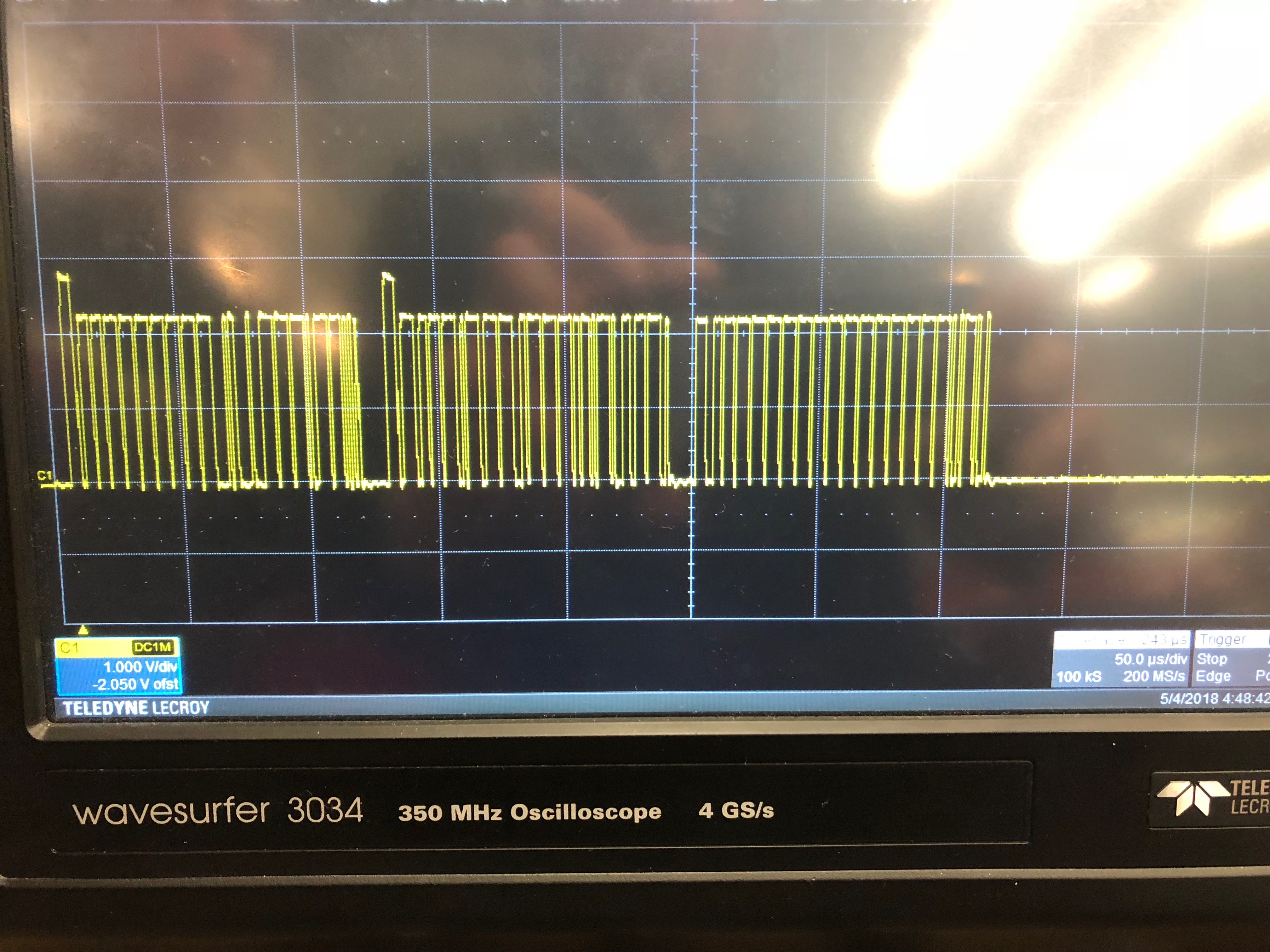
I thought this was a problem related to arbitration, but the person who set up the CAN architecture has ensured me that all IDs are different.

Any insight as to what might be going on would be greatly appreciated. Thanks!

Jason

  • Hello Jason,

    Thank you for your questions.
    Looking at your scope shot, the high VOD spikes could be attributed to the CAN acknowledge bit (ACK). For this bit, all nodes drive dominant to communicate the ACK, and so it is common to see a higher VOD on the bus for this bit. A high VOD could also occur when more than one node is driving dominant during the arbitration phase, when the nodes are communicating their ID's for bus priority.

    Would you mind providing some more information to help me better understand the issue?
    What do you mean specifically when you say that your CAN bus crashes? Did you observe a fault condition, or CAN error of some kind? It is difficult to read your screenshot clearly. How do you expect the network to behave when three nodes are connected?
    When you took this scope shot, what were the network conditions? Is only one node communicating the whole time, or multiple nodes? Did you expect more information packets to be sent, or has your communication ceased expectedly when the bus remains recessive after the third packet?

    Best Regards,
    Max Megee
  • Hi Max,

    I was helping Jason debug this issue. We were not able to capture the "moment of failure" on the scope, the above trace was an example and the question about the high level. Here are my notes on what is happening from a bus-device perspective.

    We have CANoe set up reading the CAN bus. When we have one micro powered, CAN behaves normally and spits out 3% bus load. When the second micro is plugged in (which sends the same data at same rate but with totally different CAN IDs), the bus load spikes to 70% with constant error messages. This is the state shown in the screenshot. The expected state is that there’s a total bus load of 6%.
    Also, it does not matter which combination of micros we use (there are actually using four in total, but debugging w/ 2 at a time), they all produce the same behavior as above (sending correct IDs and normal bus load when any single micro is powered, but as soon as second one is turned on the bus load reaches a very high level and then all communication stops.
    Lastly, the messages being sent are all strictly periodic – none of them are being sent in response to another message, so as far as we can tell it is not an issue with our high level code, but could be an issue in the motorware driver library if its trying to resend messages that faulted out.

  • Update from testing tonight: We were able to successfully run at 500kbps and observed no errors. This leads me to believe its a problem with the placement of the termination resistor.

    We have the physical implementation of the CANbus in more of a tree configuration instead of a "caterpillar configuration. This is shown in the image below. Note that the second termination resistor is not shown here. This is on the Vector interface connnector which plugs into the connector in the bottom left of the image.

    Do you think this is layout is problematic or could this be something else?

  • Jason,

    Yes, a star/tree network topology could introduce significant reflections onto the RS-485 bus which can affect signal integrity. This can introduce the need to decrease the bit rate in order to communicate functionally, so your being able to operate at the slower 500kbps speed seems to correlate. However, since the stub lengths in your network are pretty short, it is difficult to fully determine this as the root cause unless you are able to change the topology and see an improvement.
    Do you have the flexibility to alter the network topology?

    Best Regards,
    Max