This thread has been locked.

If you have a related question, please click the "Ask a related question" button in the top right corner. The newly created question will be automatically linked to this question.

DS125DF1610EVM: how to use DS125DF1610 as a Bert

Part Number: DS125DF1610EVM
Other Parts Discussed in Thread: DS125DF1610,

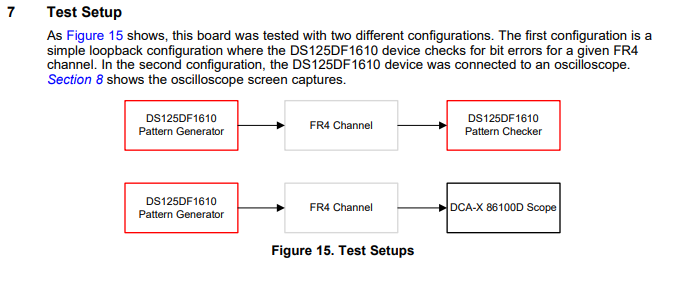
I downloaded in the Internet DS125DF1610 of the chip Design 12G 16 channel error of the instrument, the Design Numbers for TIDA - 00426 there is a document, 12 - Gbps BERT Board, the Reference Design, 18 pages in the document have a eye diagram, what connection can be eye diagram of this kind.Mainly where Trig should get it, thank you

  • Hi Kailin,

    In order to obtain an eye diagram, you can use either (1) software such as SigCon Architect to view the internal eye diagram or (2) high speed oscilloscope, like so:

    Note that the DS125DF1610 is just one of the Rx channels configured as a pattern checker.

    Is this what you are looking for? If not, please provide additional details about what you would like to do.

    Thanks,

    Michael

  • Add,How to use DS125DF1610 as a Pattern Generator,where is the RF Input and where is the Trig should be connect?
    Or,I want just use the DS125DF1610EVM to get a eye diagram, what should I do?

    thanks
  • Hi Kailin,

    1. To use the DS125DF1610 as a pattern generator, the RF input (clock signal) should be sent to any of the input Rx channels. The RF input should be a divide-by ratio of the actual data rate you wish to output.

    2. To obtain an eye diagram from the DS125DF1610EVM (internal EOM), you must provide a valid signal at the desired data rate (for example, 10.3125 Gbps) to a DS125DF1610 Rx channel. Once the DS125DF1610 channel achieves CDR lock, then you can use software such as SigCon Architect to read back the eye diagram.

    Regards,

    Michael