Dear TI experts,
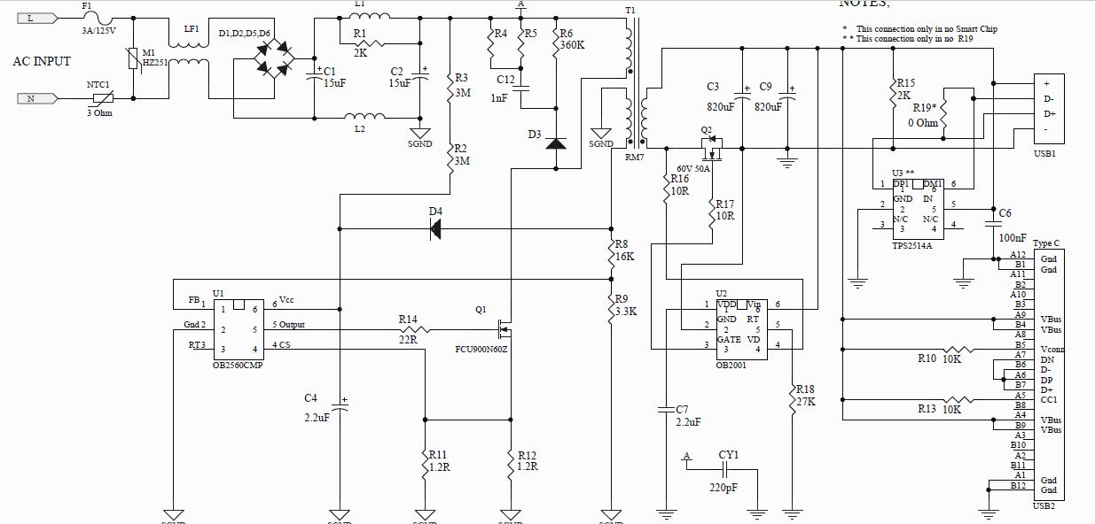
We developed a USB wall charger product based on TPS2514A. Below is the schematic for your reference. During production, we are trying to check if the product is working properly by simply measuring the voltage on DP1 and DM1 when no charging device is connected to charger. If voltage appears on both DP1 and DM1 are 2.7V/2.7V respectively, we regard the device under testing is functioning properly. Is this the correct way to verify the product? In fact, we attempted to test a few samples in this way, the voltage appears on both DP1 and DM1 are 2.7V/2.7 respectively. However, we found that there were a couple of samples exhibited quite differently, as voltages appeared on DP1 and DM1 look random.
Would you please help review the schematic and suggest proper procedures that we should employ to verify our products? Thanks, Peter.