This thread has been locked.

If you have a related question, please click the "Ask a related question" button in the top right corner. The newly created question will be automatically linked to this question.

TIR1000: duty cycle for 16Xclk

Part Number: TIR1000
Other Parts Discussed in Thread: TL16C550C, SN54LS674

Hello,

I ordered a few mpc2221 chips from Microchip. It is a small chip that is capable of converting usb signal to vitual RS232 signals. I also ordered some leds from Vishay and ... The TIR1000 from TI. So far so good. Now is the question. How can i make that pic generating the 16XCLK baud clocking signal i need??? Wel after some thinking and reading i found out the pic is capable ( running internaly on 12Mhz ) to output his clock signal !!! 12Mhz normal, can be doubled by a PLL to 24Mhz.

So I was thinking ... If i could use that pic output signal and divide it as it should i might somehow meet up with 1.843 MHz to drive the 16Xclk clock instead of the standard available 1,5MHz ???  Now 12 / 1,8 = 6,5. way off. BUT in PLLx2 mode.  24Mh  (0,5% error rate maximum as 12Mhz is calibrated to 0,25% )  /  13 =  1,846153846153846 !!!!!!! I came to the conclusion 24MHz / 13 gives a 1,6% error rate on the 115K and 38K baudrate.  But sadly ... We cannot program that pic with our own code. Just enable and set the INTclk out divider.

Now here it comes !!! Why not using a dedicated 14 bit counter ???  let us say the "74hc4060" We connect the reset line to Q13 and CLKin to the pic's 24MHz output clock. Et voila there we go.

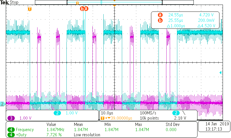
My question is. That pulsetrain wil be in pwm 1/13 instead of 50/50. So the Hz's are then nearly perfect. But duty cycle has dropped to 7,7%.  

1st Question Is:  that an issue?

2nd Question.  Will this work?

  • Hey Tom,

    This is actually a really interesting question. Typically when you supply a clock frequency (the 16x clock) the duty cycle is 50% however in your case you have a pulse which is 7.7% high and 93% low though the frequency is still 1.843MHz to support the 115k baudrate.

    This is a situation I haven't ever considered and I assume the device was designed such that the clock signals expected were to have a 50% duty cycle. The rising and falling edges for the clock are meant to be used by the device as reference to know when to sample received data and to generate data sent out at the specified clock rate (1/16 of that). What I believe will happen is the timing of when data is sampled and sent may be affected in some manner. Another possibility is the device may not do what it needs to within the high period of the clock and could ignore/miss the falling edge because it hasn't finished what it needed to do internally. (Just a guess)

    The only way I can give you a definitive answer to this would be to order some samples of the TIR1000 and do some testing. I suspect the samples will take a few days to get here and I may not be able to immediately do my tests until early next week.(I'll order samples after posting this)

    I also see that you mentioned you were using TIR2000 in your original post, this device is something which is discontinued and we no longer support. I'd like to verify whether or not your question pertains to TIR1000 or TIR2000. I am unsure if the state machine of this device is similar to each other and thus my testing may not support the TIR2000.

    Thanks,

    -Bobby

  • Hi Bobby,

    Thanks for your opinion.  Yup that TIR2000 is a typo :) I mean the TIR1000. 

    Wel as i was not going to wait for answers here i did exactly the same.  I sampled a few TIR1000's and a few CD74HC4020E from TI and my request is processed and confirmed. The 4020 is more suitable for the job as he doesn't have the internals to build a self running oscillator witch is not our goal here. Only a clock, a reset line and the 14 flipflop stages. I wil also do this testing as soon as i get the samples. Anyway also waiting for de led's and the usb/rs232 chip. So ... It wil take some time. The only reason for posting my question was to see if someone else ever tried it. In that case i don't need to reinvent hot water. If you know what i mean. 

    The problem nowadays with datasheets. They are so ... abstract. If you look at the 4020 datasheet. They almost explain every transistor in the chip. And if you look at the TIR1000 datasheet you just see the chip connections and a summary on how to use it. TI even gives some info from the internals of the "TL16C550C" witch is not even relavant to explain the TIR1000.  Just like you i don't know what happends inside. 

    My first guess is: Inside we find a 36khz free running oscillator connected to the drive for the IR led and commanded by TX. Then it also has a simple schmitt trigger opamp like input for the photo diode. The question is? Are they latched? And if they are latched. How do they latch? As you mentioned rising or falling edge? Is duty cycle a critical thing on that 16XCLK input??? No way to tell by reading the datasheet. If they are latched. I think 7.7% duty will do the job as good as the normal 50/50% pwm. Because it's puls is just needed to syncronise the internals. Either way rising or faling edge. That is not an issue. And if that is an issue. We can simply invert the Q13 with a transistor to match up with the needed input in rising or falling edge ... 

    Another possibility. We deliver 16x baudrate. But TI thinks in worst case scenarios "like ppl like me who want to deliver poor quality pwm pulses :) " and just to be sure, they devide the input frequency by /2 witch wil give them 8x baudrate and instead of counting 8 pulses til middle bitspace, they just count 4 because they already devided clk16x by2. The timebase of those pour pulses doesn't change so the counted puls nr 4 will match exactly with 16XCLK input pulse 8. BUT! This way of working will garanty them to be in a spot on 50/50% duty situation internaly ...

    I make this second guess because i did read that for this issue TI itself proposed to use a free pwm channel from the microcontroller to generate the 16baud if the chip in question does not have a dedicated baudrate out pin. They did not speak of any duty cycle value's. They only speak about frequency. Maybe they assumed that one will know they have to supply a 50/50% pwm. OR ... they didn't metion it because it's irrelevant because they perform that /2 anyway ...

    So TI. if you read this. Could you please share with us how your TIR1000 works internally. There are still ppl reading datasheets :)

    Another approach. If the HC4020 didn't get best friends with the TIR1000. ( i surely hope he does ) But if he doesn't. I might just have the answer for that 50/50% duty cycle problem.

    Could a dedicated serial shift register be the answer? If you take a look at the 74F675 witch is a 16 bit dedicated serial/parallel shift register. We connect the 24Mhz to it's clock. We don't use any read/write and we disable it's reset line so he keeps on running free. BUT!!!  We invert his Q13 with a simple transistor and feed that to the Data in latch as wel as to the 16XCLK input of the TIR1000. The end result: In the beginning. no clock, Q13 in low state, transistor feeds a logic 1 to the serial data latch, 1 pulse, Q13 still low, data in still 1, pulse2, pulse3, ... Until pulse 13. Q13 get's active and thus inverts the transistor terminal and thus starts to feed 0's to the data in latch. same for pulse 14, because the whole register up to 13 was filled with 1's. same for 15, same for 16, .... until pulse 26. Again Q13 shifts in a binary 0, flips the transistor and on, and on, ...  

    End result? We still effectively do a 24Mhz / 13 ( as we shift 13 clocks until something happends ) to get our 16XCLK @ the right speed. BUT this time we don't do any reset's we let the register do the bitshifting and in fact we now use the data latch in as our 16xbaudrate signal but this one now is @ the correct 50/50 duty cycle.

    I also ordered the shift register. I Will do tests on both methods anyway!  The one small problem. That typical register of TI is called the SN54LS674 for a reason. After checking the datasheet. This one "LS" can only handle speeds up to 20MHz. Witch is obviously to slow for 24Mhz. Fairshild does have a 74F675A 16-bit shift register capable of minimum 100MHz. We just need to connect the write pin to the main clock to make the shifting visual to it's outputs ... But as i found out. Those parts are obsolete. You can stil find some. But production has stopped ...

    Another sollution would be to program a second pic. 12F1840 to name one. Program his eusart for autobaud and make him feed the 0% error perfect 16xbaudrate tot the PIR1000. That would mean even if you change the baudrate and you always send the "U" first. You can select any baudrate you want. The trick here would be to stick to 115 and 38 Kbaud. Al other speeds can't be made with the /13 divider trick. But as you can imagine. I think that's just stupid. Then you could have programmed a usb capable pic. Implement the cdc stack yourself and use an internal timer to generate baudx16. But this is not what i intend to do here. I intend to buy the converter chip who is programmed by factory for his task. Use it as it is intended to be used. And ... If needed add 1 or two parts to arrange some stuff. Not a single letter of code is written. Ready to go product ...

    Again another idea would be to just use one of those ftdi chips. But they are not that cheap and also don't deliver a baudrate out clk. So the problem even get's more complicated then with the preprogrammed pic solution. + after what they have done to their end users, they will never ever again receive any order for any part of me. Weaponizing your official driver to battle counterfeit is just not done. They had other methods to deal with the situation. So ... in any case ftdi is no where near an option for me. I don't like their style nor the chip price and the hardware get's more complicated ...

    What do you think of this?

    Best Regards,

    Tom

  • I do agree with the fact that a full implementation of the cdc stack inside a capable controllerchip is the best / most ellegant sollution for this job. All ( even non standard ) baudrates would be available to the end user. As we generate the baudrate for aur own uart. We certainly can deliver that exact value to the TIR1000. But before you can do that. You need to understand how that stack works :) --> reason that for now. I want to use a ready to go converter + maybe some extra hardware ...

  • Hey Tom,

    My samples came in today, I'll solder some on a breakout board and try to get to testing tomorrow.

    I'll let you know!
    -Bobby
  • Hey Tom,

    Sorry for my delay in response. I was able to get in the lab today and perform testing.

    I used an Agilent 33220A function generator to get the 1.846MHz clock at a ~7.7% duty cycle. You can see my measurements on the clock signal below.

    I would say this looks pretty good.

    So I set up a mcu to send through serial 0xAA into the U_TXD of TIR1000 and then monitored IR_TXD:

    Please excuse the crosstalk. I set all this up the TIR1000 on a breakout board and long wires and this was the result.

    Blue is the input: U_TXD

    Purple is the output: IR_TXD

    Looks like duty cycle doesn't matter for transmitting. So now we need to ask, what about receiving?

    Well, I decided the easiest thing to do to verify this is to just short IR_TXD to IR_RXD and the input should match the output with some delay.

    Blue is the input: U_TXD
    Purple is the output: IR_TXD

    Green is the output: U_RXD

    From this we can successfully say that the transmit and receive inputs successfully work with a duty cycle that is 7.7%. I also believe the U_TXD is falling edge rate triggered while the IR_RXD is rising edge triggered.

    Thanks!

    -Bobby

  • Thank you Bobby!

    I will build the idea and let you know the results.

    Still waiting for some samples.

    Tom