This thread has been locked.

If you have a related question, please click the "Ask a related question" button in the top right corner. The newly created question will be automatically linked to this question.

TUSB542EVM: pin assign is different between datasheet and EVM

Guru 29690 points
Part Number: TUSB542EVM
Other Parts Discussed in Thread: TUSB542

Hi Team,

There is different pin assign between datasheet and EVM as the following.
--------------------------------------------------------
- TUSB542 datsheet


-TUSB542EVM

--------------------------------------------------------
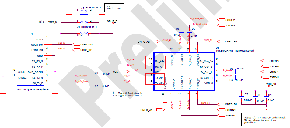
I believe datasheet is correct. Is my understanding correct?
If EVM is typo, could you tell me which is typo pin name or pin number?

Best Regards,
Yaita

  • Yaita-san

    The datasheet is correct, we need to update the schematic file.

    Pin 14 and 15 is TX_AP+/- which are input. Pin 17 and 18 are RX_AP+/- which are output.

    Thanks
    David
  • Hi David-san,

    Do you refer pin number is typo in schematic of EVM?
    I would like to confirm which C1/C2 should be connected to TX_AP or RX_AP.
    Is it TX_AP?

    Best Regards,
    Yaita

  • Yaita-san

    The pin name in the EVM needs to be updated.

    RX_AP+/- (pin 17 and 18) is the output, which needs to be AC coupled (C1 and C2).

    TX_AP+/- (pin 14 and 15) is the input, since the AC coupling caps are on the corresponding TX, then there is no need for AC coupling caps. Please note that in the latest USB ECN, they do recommend optional 330uF cap on TX_AP+/- on the receiver side. 


    Thanks
    David

  • Hi David-san,

    Thank you for your continuous support.
    I understand the following schematic is the correct.


    >Please note that in the latest USB ECN, they do recommend optional 330uF cap on TX_AP+/- on the receiver side. 
    I would like to ask further question about your comment above.

    1)
    I think 330uF is typo and 330nF is correct.
    Is my understanding correct?

    2)
    Regarding USB3.1 ECN, I believe it is recommeded to put four AC caps at red dot line.
    Not only TX_AP+/- of Type-B receptacle but also RX_CON_2+/- of Type-C receptacle.
    Is my understanding correct?

    Best Regards,
    Yaita

  • Yaita-san

    Your updated schematic is correct.

    1) 330uF is a typo on my part, it should be 330nF.
    2) This is correct.

    Thanks
    David
  • David-san,

    I really appreciate for your support.
    I understand.

    Best Regards,
    Yaita