This thread has been locked.

If you have a related question, please click the "Ask a related question" button in the top right corner. The newly created question will be automatically linked to this question.

DS90UB953-Q1: Pattern generation for YUV422

Part Number: DS90UB953-Q1
Other Parts Discussed in Thread: ALP

Hi team,

We are thinking of using 953 pattern generate in YUV422 format.

Could you provide any script or code for YUV422 8bit?

And I have also general questions about pattern generation.

#1

How should I set up the front porch and the back porch?

Should the display have a request?

#2

Are there any restrictions on total line per frame?

I do not understand how to set the total line per frame.

For example, is there no problem with the setting of 500 active lines and 1000 total lines per frame?

We think that there is no problem while satisfying the FPD-LINK data rate as it only increases blanking.

Best regards,

Tomoaki Yoshida

  • Hello Tomoaki-san,

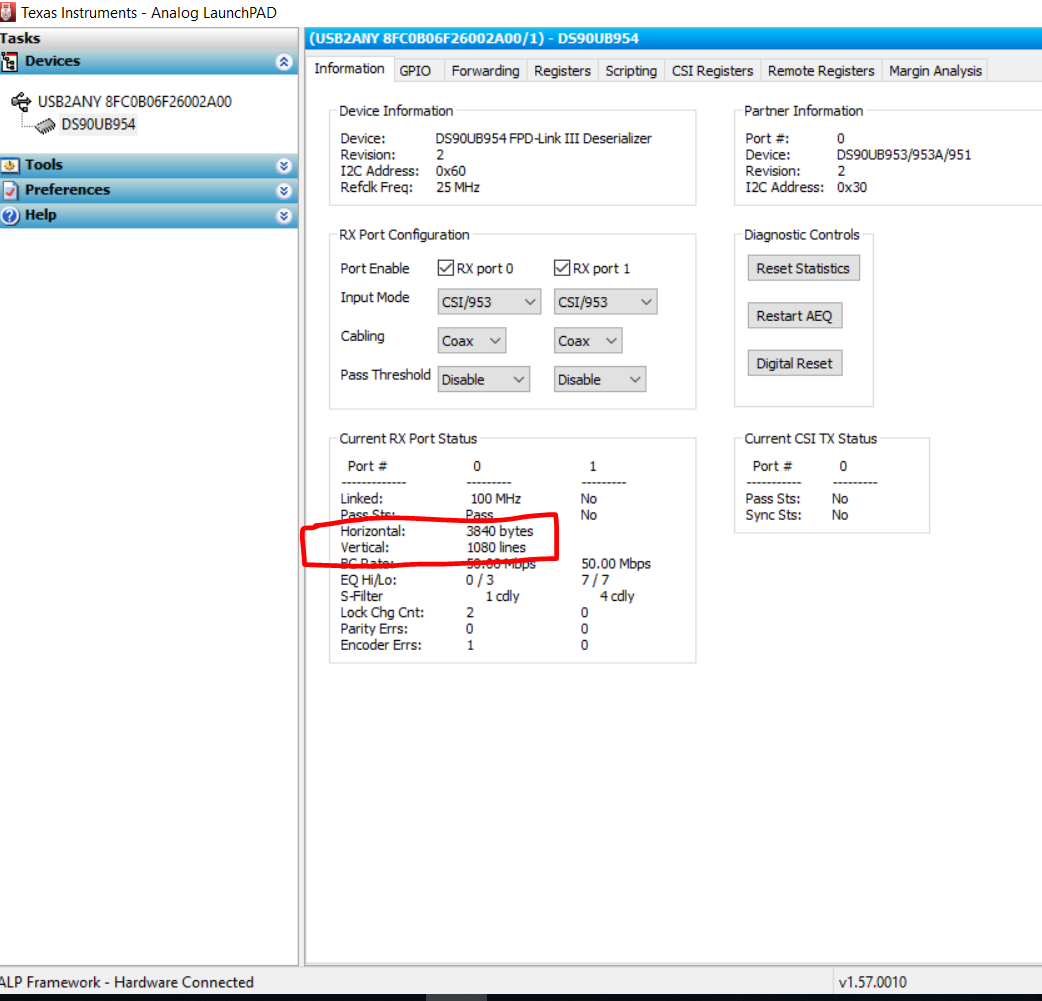
    I have enclosed here an example script for UB953 Patgen YUV422 8bit (1920x1080p) format. With 954/953 EVM setup you can run this from ALP 954 script window to see horizontal/vertical data as shown below.

    953to954_patgen_YUV_1920x1080p-4Lanes-Working.py
    """
      Copyright 2018 Texas Instruments Incorporated. All rights reserved.
    
      IMPORTANT: Your use of this Software is limited to those specific rights
      granted under the terms of a software license agreement between the user who
      downloaded the software, his/her employer (which must be your employer) and
      Texas Instruments Incorporated (the "License"). You may not use this Software
      unless you agree to abide by the terms of the License. The License limits your
      use, and you acknowledge, that the Software may not be modified, copied or
      distributed unless embedded on a Texas Instruments microcontroller which is
      integrated into your product. Other than for the foregoing purpose, you may
      not use, reproduce, copy, prepare derivative works of, modify, distribute,
      perform, display or sell this Software and/or its documentation for any
      purpose.
    
      YOU FURTHER ACKNOWLEDGE AND AGREE THAT THE SOFTWARE AND DOCUMENTATION ARE
      PROVIDED AS IS WITHOUT WARRANTY OF ANY KIND, EITHER EXPRESS OR IMPLIED,
      INCLUDING WITHOUT LIMITATION, ANY WARRANTY OF MERCHANTABILITY, TITLE,
      NON-INFRINGEMENT AND FITNESS FOR A PARTICULAR PURPOSE. IN NO EVENT SHALL TEXAS
      INSTRUMENTS OR ITS LICENSORS BE LIABLE OR OBLIGATED UNDER CONTRACT,
      NEGLIGENCE, STRICT LIABILITY, CONTRIBUTION, BREACH OF WARRANTY, OR OTHER LEGAL
      EQUITABLE THEORY ANY DIRECT OR INDIRECT DAMAGES OR EXPENSES INCLUDING BUT NOT
      LIMITED TO ANY INCIDENTAL, SPECIAL, INDIRECT, PUNITIVE OR CONSEQUENTIAL
      DAMAGES, LOST PROFITS OR LOST DATA, COST OF PROCUREMENT OF SUBSTITUTE GOODS,
      TECHNOLOGY, SERVICES, OR ANY CLAIMS BY THIRD PARTIES (INCLUDING BUT NOT
      LIMITED TO ANY DEFENSE THEREOF), OR OTHER SIMILAR COSTS.
    
      Should you have any questions regarding your right to use this Software,
      contact Texas Instruments Incorporated at www.TI.com.
    
    """
    # Patgen YUV ColorBar 1920x1080p30 on 953/954
    # Version 0.92
    
    import time
    
    # 953 config
    runTime = 3
    
    Alias953 = 0x18
    DES954 = 0x60
    
    
    # Reset 954
    board.WriteI2C(DES954, 0x01, 0x01)
    time.sleep(1.0)
    # CSI enable , continuous clock, 4 lanes
    board.WriteI2C(DES954, 0x33, 0x03)
    time.sleep(0.1)
    # Set CSI_TX_SPEED to select 800Mbps
    board.WriteI2C(DES954, 0x1F, 0x02)
    time.sleep(0.1)
    # Port Control
    board.WriteI2C(DES954, 0x0C, 0x83)
    time.sleep(0.1)
    # Port Selection
    board.WriteI2C(DES954, 0x4C, 0x01)
    time.sleep(0.1)
    # set alias
    board.WriteI2C(DES954, 0x5C, 0x18)
    time.sleep(0.1)
    board.WriteI2C(DES954, 0x20,0x00) # forwarding of all RX to CSI0
    time.sleep(0.1)
    if (board.ReadI2C(Alias953, 0x00, 0x01) != 0x30):
    	print "953 ID Error"
    else:
    	print "953 ID Ok"
    
    # Reset 953
    board.WriteI2C(Alias953, 0x01, 0x01)
    time.sleep(1.0)	
    # enable pat gen
    board.WriteI2C(Alias953, 0xB0, 0x00)
    board.WriteI2C(Alias953, 0xB1, 0x01)
    board.WriteI2C(Alias953, 0xB2, 0x01) #enable pattern generator
    
    board.WriteI2C(Alias953, 0xB1, 0x02)
    board.WriteI2C(Alias953, 0xB2, 0x33) #fixed color pattern, 8 color bars, block size of 5
    
    board.WriteI2C(Alias953, 0xB1, 0x03)
    board.WriteI2C(Alias953, 0xB2, 0x1E) #CSI Data Identifier (0x24 = RGB888, 0x2C = RAW12, 0x2B = RAW10)
    
    board.WriteI2C(Alias953, 0xB1, 0x04)
    board.WriteI2C(Alias953, 0xB2, 0x0f) #line size (15:8)
    
    board.WriteI2C(Alias953, 0xB1, 0x05)
    board.WriteI2C(Alias953, 0xB2, 0x00) #line size (7:0)
    
    board.WriteI2C(Alias953, 0xB1, 0x06)
    board.WriteI2C(Alias953, 0xB2, 0x01) #bar size (15:8)
    
    board.WriteI2C(Alias953, 0xB1, 0x07)
    board.WriteI2C(Alias953, 0xB2, 0xe0) #bar size (7:0)
    
    board.WriteI2C(Alias953, 0xB1, 0x08)
    board.WriteI2C(Alias953, 0xB2, 0x04) #active lines per frame (15:8)
    
    board.WriteI2C(Alias953, 0xB1, 0x09)
    board.WriteI2C(Alias953, 0xB2, 0x38) #active lines per frame (7:0)
    
    board.WriteI2C(Alias953, 0xB1, 0x0a)
    board.WriteI2C(Alias953, 0xB2, 0x04) #total lines per frame (15:8)
    
    board.WriteI2C(Alias953, 0xB1, 0x0b)
    board.WriteI2C(Alias953, 0xB2, 0x65) #total lines per frame (7:0)
    
    board.WriteI2C(Alias953, 0xB1, 0x0c)
    board.WriteI2C(Alias953, 0xB2, 0x0b) #line period (15:8)
    
    board.WriteI2C(Alias953, 0xB1, 0x0d)
    board.WriteI2C(Alias953, 0xB2, 0x93) #line period (7:0)
    
    board.WriteI2C(Alias953, 0xB1, 0x0e)
    board.WriteI2C(Alias953, 0xB2, 0x21) #vertical back porch
    
    board.WriteI2C(Alias953, 0xB1, 0x0f)
    board.WriteI2C(Alias953, 0xB2, 0x0a) #vertical front porch
    
    board.WriteI2C(Alias953, 0xB1, 0x10) 
    board.WriteI2C(Alias953, 0xB2, 0x00) #1st byte of fixed color
    
    board.WriteI2C(Alias953, 0xB1, 0x11)
    board.WriteI2C(Alias953, 0xB2, 0x00) #2nd byte of fixed color
    
    board.WriteI2C(Alias953, 0xB1, 0x12)
    board.WriteI2C(Alias953, 0xB2, 0xFF) #3rd byte of fixed color
    
    # board.WriteI2C(0xB1, 0x13)
    # board.WriteI2C(0xB2, 0xff) #4th byte of fixed color
    
    # board.WriteI2C(0xB1, 0x14)
    # board.WriteI2C(0xB2, 0xff) #5th byte of fixed color
    
    # board.WriteI2C(0xB1, 0x15)
    # board.WriteI2C(0xB2, 0x00) #6th byte of fixed color
    
    # board.WriteI2C(0xB1, 0x16)
    # board.WriteI2C(0xB2, 0x00) #7th byte of fixed color
    
    # board.WriteI2C(0xB1, 0x17)
    # board.WriteI2C(0xB2, 0x0f) #8th byte of fixed color
    
    # board.WriteI2C(0xB1, 0x18)
    # board.WriteI2C(0xB2, 0xf0) #9th byte of fixed color
    
    # board.WriteI2C(0xB1, 0x19)
    # board.WriteI2C(0xB2, 0x00) #10th byte of fixed color
    
    # board.WriteI2C(0xB1, 0x1A)
    # board.WriteI2C(0xB2, 0x00) #11th byte of fixed color
    
    # board.WriteI2C(0xB1, 0x1B)
    # board.WriteI2C(0xB1, 0x3f) #12th byte of fixed color
    
    # board.WriteI2C(0xB1, 0x1C)
    # board.WriteI2C(0xB2, 0xc0) #13th byte of fixed color
    
    # board.WriteI2C(0xB1, 0x1D)
    # board.WriteI2C(0xB2, 0x00) #14th byte of fixed color
    
    # board.WriteI2C(0xB1, 0x1E)
    # board.WriteI2C(0xB2, 0x00) #15th byte of fixed color
    
    # board.WriteI2C(0xB1, 0x1F)
    # board.WriteI2C(0xB2, 0x00) #16th byte of fixed color


    #1. Yes, front porch and back porch depends on the display. About 10%.

    #2. Total lines = Active lines + Blanking (vertical front porch + vertical back porch + vertical sync)

    With example script above you can see how to set the various parameters.

    Thanks,

    Vishy

  • Hi Vishy-san,

    Thank you for your support.
    It was very helpful for us.

    In our system, we have no display and let the SoC to handle data.
    So, we can not directly confirm the image generated by the pattern generator.
    We want to use a pattern generator to analyze the data and see if the data in each pixel is as expected.

    Could you tell me the expected value of pixel data for each bar in case of 8 color pattern setting?

    Best regards,
    Tomoaki Yoshida
  • Hi Vishy-san,

    Thank you for your support.
    We will refer to the attached script.
    This script seems to be set to 30 fps, but if we want to set it to 60 fps, we will change only PGEN_LINE_PD?
    In this case, cut the time in half.

    Best regards,
    Tomoaki Yoshida
  • >>>This script seems to be set to 30 fps, but if we want to set it to 60 fps, we will change only PGEN_LINE_PD?

    Yes. You need to update line period loaded in indirect registers 0x0c, 0x0d (script code line numbers 108, 111).. Line period is given in 10ns units. It is based on frame rate and total lines per frame. In the example script, line period is calculated using 30fps and 1125 total lines using formula (1/(30fps x 1125linesperframe x 10ns)).

    >>>>Could you tell me the expected value of pixel data for each bar in case of 8 color pattern setting?
    Values loaded in indirect registers 0x10, 0x11, 0x12

    Thanks,
    Vishy
  • Hi Vishy-san,

    Thank you for your support.

    I do not yet understand the expected values of the color bar pattern pixel data.

    The indirect address 0x10, 0x11, 0x12 is described as the byte data of each color bar. For example, 0x10 is color bar 0 byte data and 0x11 is color bar 1 byte data.

    In the case of YUV422 8 bit, it becomes 2 byte data per pixel, but what is the relationship with 0x10?

    Please look at the attached document if my understanding is correct.

    /cfs-file/__key/communityserver-discussions-components-files/138/YUV422_2D00_8bit-pattern-gen.pdf

    I understand that it will be set as attached from the script that was taught in the previous email.

    Could you tell me the relationship between U0, Y0, V0, Y1 of color bar 0 and the byte data of indirect address 0x10.

    Best regards,

    Tomoaki Yoshida

  • Hi Vishy-san,

    Thank you for your support.

    In this script, U0 [7: 0] = Y0 [7: 0] = V0 [7: 0] = Y1 [7: 0] = 0xAA for color bar pattern 0, and this value is within the set color bar size.
    In this case, the Color Bar pixel size is 240pxl.
    U240 [7: 0] = Y240 [7: 0] = V240 [7: 0] = Y241 [7: 0] = 0x33 of the color bar pattern 1.
    Is this correct?

    Best regards,
    Tomoaki Yoshida
  • Hello Tomoaki-san,

    I am checking about this. The default value for color bar pattern 0 and color bar pattern1 in DS90UB954 data sheet (Table 200 and 201) is 0xAA and 0x33. So I think you are right.

    thanks,
    Vishy
  • Hi Vishy-san,

    Thnak you for your support.

    I have an additional question for the following formula that you wrote earlier.

    #2. Total lines = Active lines + Blanking (vertical front porch + vertical back porch + vertical sync)

    I saw some sample code and script files, but they are all set vertical sync is 2.

    Does this mean that 954 needs at least 2?

    Or should it be system dependent and decided from display requirements?

    I want to know where the number 2 should be determined.

    Best regards,

    Tomoaki Yoshida

  • Hello Tomoaki-san

    It depends on display. Generally the vertical sync signal indicates beginning of a new image or frame. The horizontal sync indicates beginning of another row of pixels. After (say) 1080 rows of pixels a vertical sync indicates end of frame (resets display to the upper left corner) and the process continues. You can google on this and find a number of references.

    Thanks,

    Vishy

  • Hello Tomoaki-san,

    Forgot to mention...Please also take a look at this TI app note (if you have not already) on pattern generator
    www.ti.com/.../snla132c.pdf

    Thanks,
    Vishy
  • Hi Vishy-san,

    Thank you for your support.
    I understand much thanks to your explanation.

    The way to adjust the width of vsync to the display requirements is to change the Total lines.
    vertical sync = Total lines - (Active lines + vertical front porch + vertical back porch)

    There is no register to adjust Vsync directly, so I understand that I adjust by Total lines.
    Please point out if there is a mistake.

    Best regards,
    Tomoaki Yoshida
  • Tomoaki-san,
    Yes, you are right. There are registers to define active lines per frame, total lines per frame, vertical back porch and vertical front porch. You can adjust vsync size by changing total lines per frame.
    Thanks,
    Vishy