This thread has been locked.

If you have a related question, please click the "Ask a related question" button in the top right corner. The newly created question will be automatically linked to this question.

TIC12400EVM-KIT: ABPOUT MSP430 LED

Part Number: TIC12400EVM-KIT
Other Parts Discussed in Thread: TIC12400

Hi TI-team

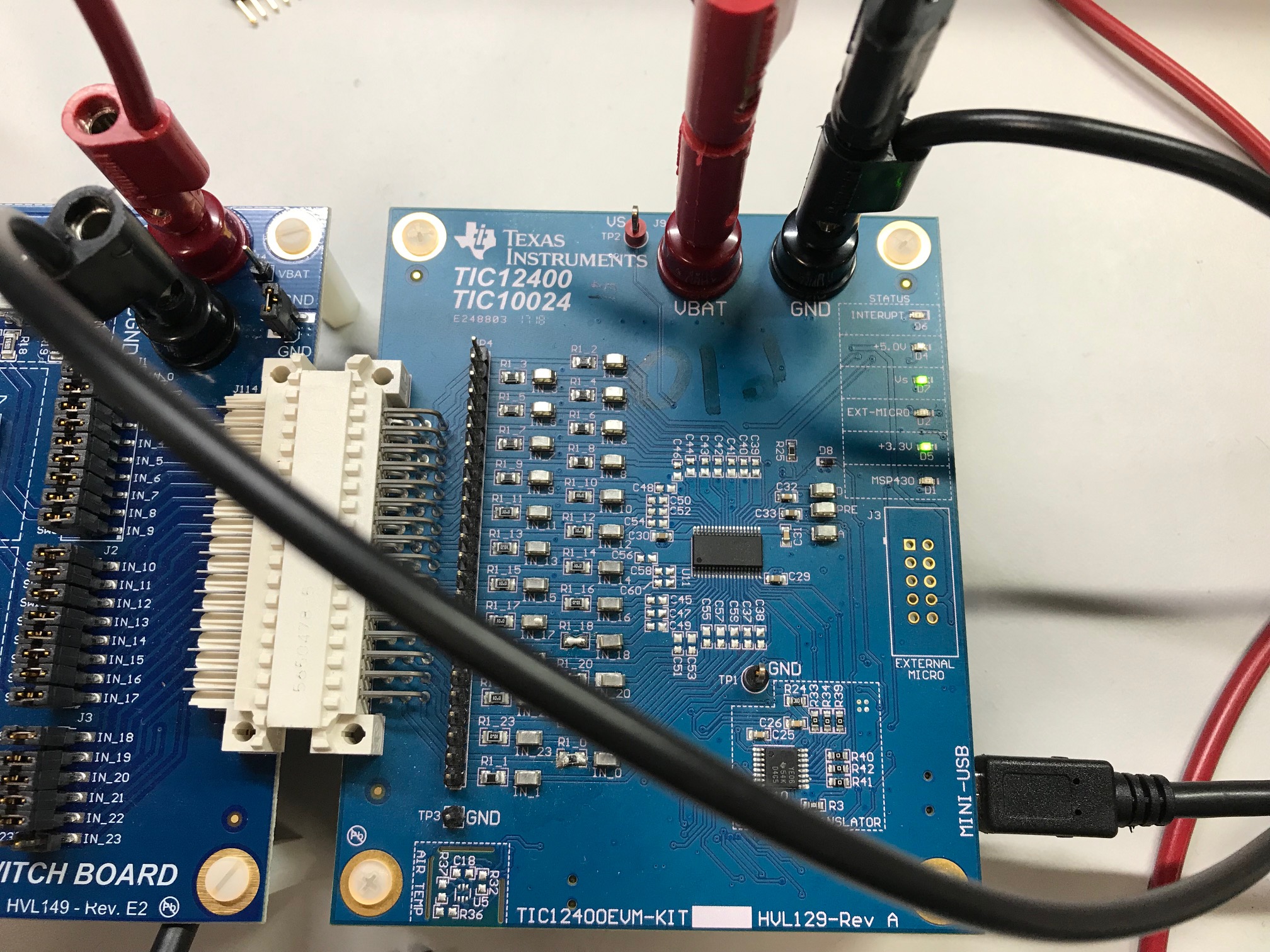
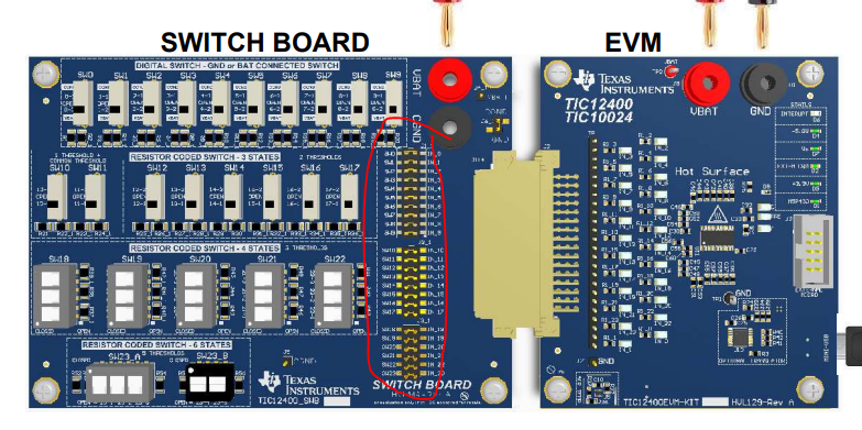
I want to connect the STITCH BOARD to the TIC12400EVM-KIT and check the operation.
I have read the TIC12400 EVM User's Guide but it does not work well.
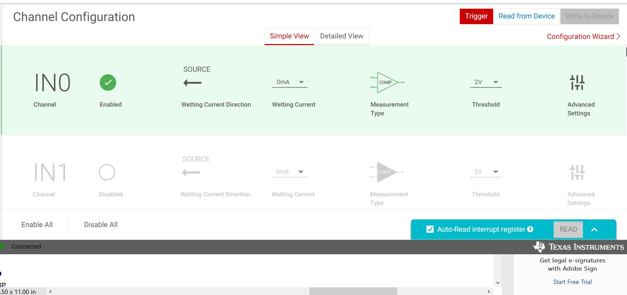
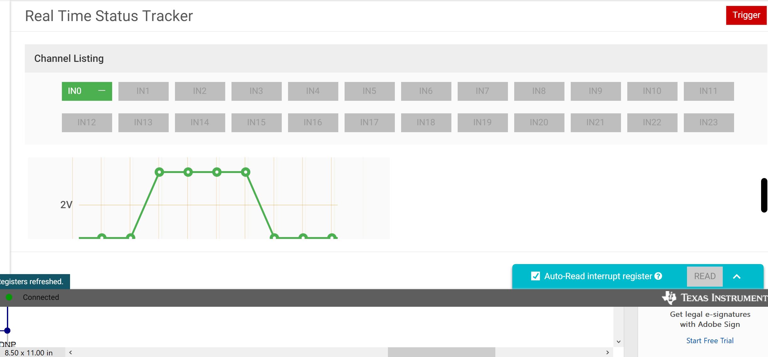
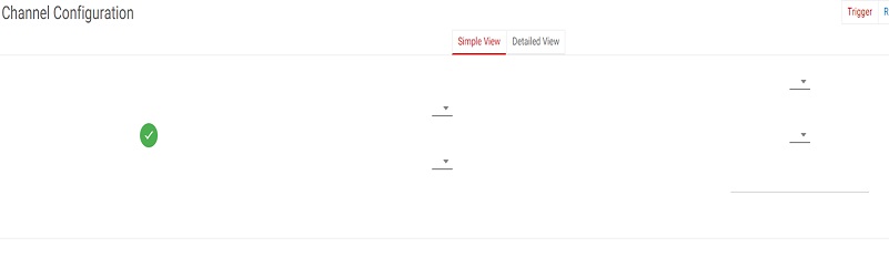
There is no change in Real Time Status Tracker even when switching SW0.
The same applies to other switches.

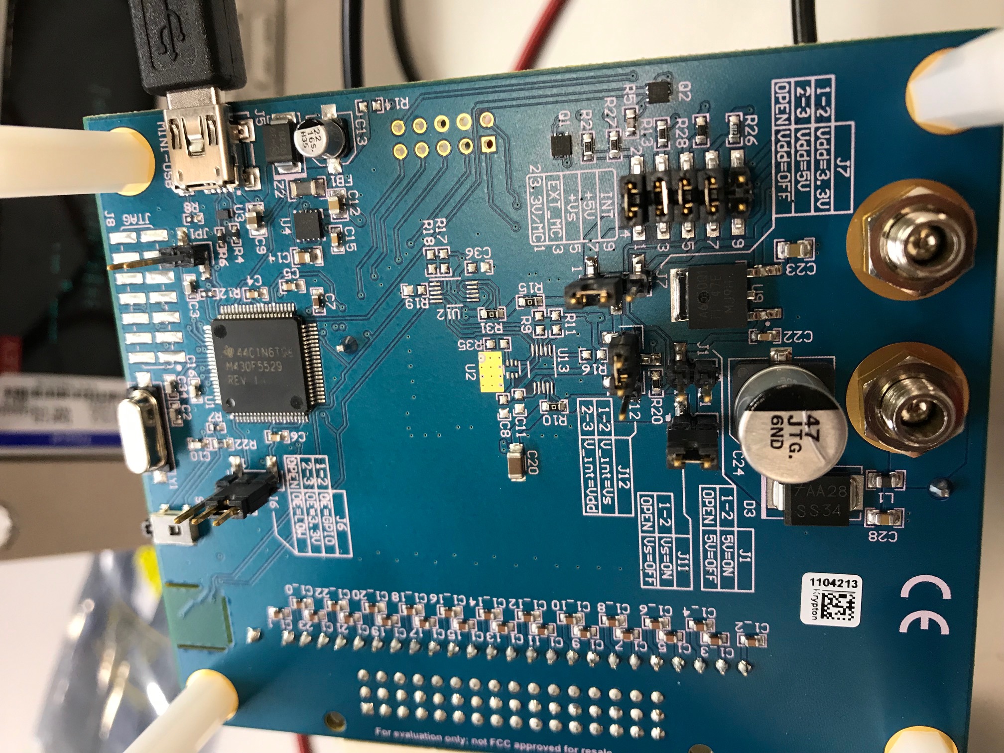
I noticed that the MSP430 LED on D1 is not illuminated.
When does this LED come on ?
I would like to confirm that the voltage changes due to the switch ON/OFF.
 
Best Regards,
Koji Hayashi
  • Koji,

    I went to check if I could get the real time tracker to confirm the voltage change due to the switch on and off. 

    Here are pictures of my LEDs. 

    Here are my jumper configurations.

    Next is my GUI settings for the SW0.  I turned on IN0 which is connected to SW0 through the large J114 connector.  Make sure the jumper J1 on the switch board is shorting SW0 to IN0.  

    Here you can see where I used the real time tracker to show I toggled switch 0 from high (3.3V) across the 2V threshold set above and then back down to ground.

    Are you able to read and write to the device through the GUI?

    Thank you,

    Adam

  • Hi Adam-san

    Thank you for response.

    It worked normally.

    However, sometimes the initial value is strange.
    There are times when all the registers are High.
    When I look at "Real Time Status Tracker", it starts with the condition being triggered.
    Is the setting wrong?
     
    Also, when I look at "Channel Configuration", it is the following image.
    Has Adam-san ever seen this ?
     
    Best Regards,
    Koji Hayashi
  • Koji,

    I have not seen that issue in your image where the GUI isn't rendering properly.  The GUI was written when we were using windows 7.  What operating system are you using to run the GUI?

    Thank you,

    Adam

  • Hi Adam-san

    Thank you for response.

    I use windows10 and GUI version is v1.0.0.

    How about this matter ?

    There are times when all the registers are High.


    Best Regards,

    Koji Hayashi

  • Koji-san,

    I use a computer with windows 10 as well and haven't had any issues so far. 

    What is your start up procedure that you see all registers high? 

    Do you have any issues after you program the registers to the settings you want?

    Thank you,

    Adam

  • Koji,

    We haven't heard from you in a while so I will assume that you resolved your issue. I'm going to close this thread and if you have additional questions replying here will reopen it or you may post a new thread.

    Thank you,

    Adam

  • Hi Adam-san

    I apologize for this late reply.

    1 Launch the GUI (At this time, all registers are Low)
    2 Cnnect the EVM
    3 Read Register  (At this time, all registers are High)
    VBAT voltage is not given.
     
    Please tell me how to set it up correctly.
    What should I do to initialize register ?
    Best Regards,
    Koji Hayshi
  • Hi, Hayshi-san,

    Please try connecting the EVM first before starting the GUI and make sure you apply the power to the device first. 

    Once the GUI is started, the registers should refresh itself and you should be able to read the default register values (ex: 20h on the DEVICE_ID). If the default register values are not right, it means something is not set up correctly. 

    Are you reading the default register values?

    If it's still not working, please send me the configuration file (.JSON) by going to File--> Save As and I can check your setting for you.

    Regards,
    David

  • Hi David-san


    Thank you for response.


    In the above order, all registers were High.
    So I turned off and on the 12V power once with the GUI up and USB connected.


    The red LED of INTERRUPT turned on.
    I clicked on ALL REGISTERS in registers to reload registers.
    The red LED of INTERRUPT turned off.
    DEVICED_ID was 11h.

    I attached a configuration file.
    Please confirm attached file.

    I changed the extension from .json to .txt.

    tic12400EVM.json.txt
    {"signature":"oneui-register-data","data":[[{"idx":0,"id":"device_id","value":"0x11"},{"idx":1,"id":"int_stat","value":"0x1"},{"idx":2,"id":"crc","value":"0xFFFF"},{"idx":3,"id":"in_stat_misc","value":"0x0"},{"idx":4,"id":"in_stat_comp","value":"0x0"},{"idx":5,"id":"in_stat_adc0","value":"0x0"},{"idx":6,"id":"in_stat_adc1","value":"0x0"},{"idx":7,"id":"in_stat_matrix0","value":"0x0"},{"idx":8,"id":"in_stat_matrix1","value":"0x0"},{"idx":9,"id":"ana_stat0","value":"0x0"},{"idx":10,"id":"ana_stat1","value":"0x0"},{"idx":11,"id":"ana_stat2","value":"0x0"},{"idx":12,"id":"ana_stat3","value":"0x0"},{"idx":13,"id":"ana_stat4","value":"0x0"},{"idx":14,"id":"ana_stat5","value":"0x0"},{"idx":15,"id":"ana_stat6","value":"0x0"},{"idx":16,"id":"ana_stat7","value":"0x0"},{"idx":17,"id":"ana_stat8","value":"0x0"},{"idx":18,"id":"ana_stat9","value":"0x0"},{"idx":19,"id":"ana_stat10","value":"0x0"},{"idx":20,"id":"ana_stat11","value":"0x0"},{"idx":21,"id":"ana_stat12","value":"0x0"},{"idx":22,"id":"config","value":"0x0"},{"idx":23,"id":"in_en","value":"0x0"},{"idx":24,"id":"cs_select","value":"0x0"},{"idx":25,"id":"wc_cfg0","value":"0x0"},{"idx":26,"id":"wc_cfg1","value":"0x0"},{"idx":27,"id":"ccp_cfg0","value":"0x0"},{"idx":28,"id":"ccp_cfg1","value":"0x0"},{"idx":29,"id":"thres_comp","value":"0x0"},{"idx":30,"id":"int_en_comp1","value":"0x0"},{"idx":31,"id":"int_en_comp2","value":"0x0"},{"idx":32,"id":"int_en_cfg_0","value":"0x0"},{"idx":33,"id":"int_en_cfg_1","value":"0x0"},{"idx":34,"id":"int_en_cfg_2","value":"0x0"},{"idx":35,"id":"int_en_cfg_3","value":"0x0"},{"idx":36,"id":"int_en_cfg_4","value":"0x0"},{"idx":37,"id":"thres_cfg0","value":"0x0"},{"idx":38,"id":"thres_cfg1","value":"0x0"},{"idx":39,"id":"thres_cfg2","value":"0x0"},{"idx":40,"id":"thres_cfg3","value":"0x0"},{"idx":41,"id":"thres_cfg4","value":"0x0"},{"idx":42,"id":"thresmap_cfg0","value":"0x0"},{"idx":43,"id":"thresmap_cfg1","value":"0x0"},{"idx":44,"id":"thresmap_cfg2","value":"0x0"},{"idx":45,"id":"matrix","value":"0x0"},{"idx":46,"id":"mode","value":"0x0"}]]}

    The setting of the back of EVM is as follows.

    J1: Open
    J4: INT Open  OTHER Short
    J7: Vdd=3.3V
    J11: Vs=ON
    J12: Vint=Vdd
    J6: OE=GPIO
    JP1: Open

    I think it is the same as your settings.


    Best Regards,
    Koji Hayashi

  • Hi, Hayashi-san,

    If you could read  device ID (either 11h or 20h) back and be able to read FFFF on the CRC register, that means you are communicating to the device and able to read the registers, which is a good sign.  

    Can you let me know exactly what's the issue you are facing now? You mentioned "There is no change in Real Time Status Tracker even when switching SW0". Is that still the case? If so, can you let me know how you set up the threshold for IN0, the wetting current...etc? You could also send me the .JSON file after you complete the setup so I can debug it for you.

    Also keep in mind you have to have the jumpers (see below) installed on the switch board for the channels you want to monitor, otherwise toggling the physical switch will not do anything. 

    Regards,
    David

  • Hi David-san

    Thank you for response.

    I want to know how to start up correctly.

    When activated, all registers are 1.

    Currently, I am “operating” in the order I posted on 8/2.

    "Operating" means that Real Time Status Tracker is High / Low when SW0 is High / Low.

    Also, my device ID is 11h but data sheet's ID is 20h.

    Is there a problem due to the difference in ID ?
     
    I have a jumper setting.
     
    Best Regards,
    Koji Hayashi