Hello team,
When I was testing the threshold parameter of the reciever refering to the datasheet, two methods were used and their results are different.
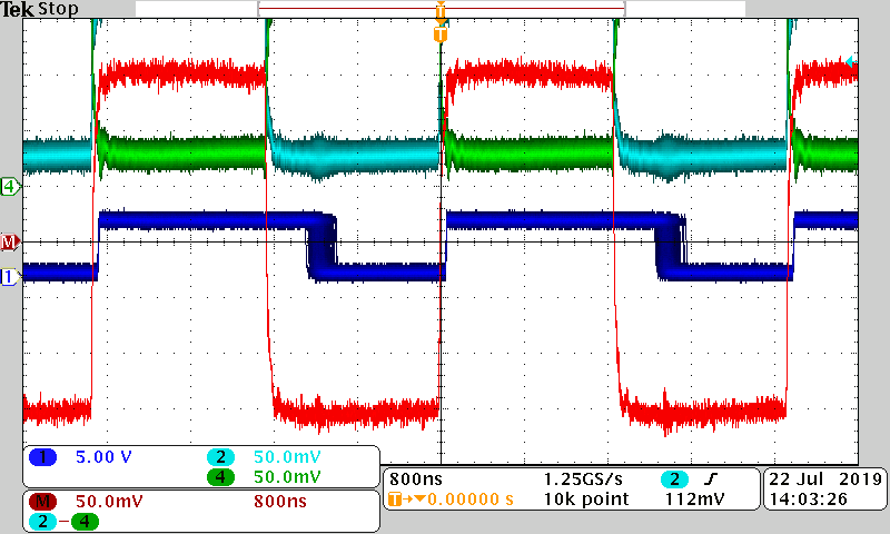
The first method is adding a squarewave directly to the two input pins of the reciever, and by changing its high level and low level, we can get the threshold voltage when the receiver is not able to maintain a determined output, as shown above;
The second is adding a common mode voltage between -7~12V at the input side, and we use a signal generator to add a squarewave as the differential mode signal, a transformer is used for isolation, as shown below
However, this method is only able to change the peak-peak voltage of the signal, and when it is lower than 700mV, the output is not able to maintain a stable voltage, so the threshold voltage is much higher than the given range on the datasheet.
So which of the testing method is correct? and why these two method lead to different results?
Thanks a lot.