This thread has been locked.

If you have a related question, please click the "Ask a related question" button in the top right corner. The newly created question will be automatically linked to this question.

SN65HVD1782-Q1: What is the parasitic capacitance requirement for TVS devices?

Part Number: SN65HVD1782-Q1
Other Parts Discussed in Thread: THVD2450, SN65HVD1782,

Dear team,

1. What is the parasitic capacitance requirement for TVS devices when RS485 is operating at 10MHz? Less than 10pF? 20pF?

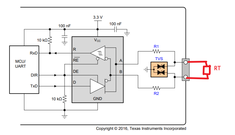
2. What are the function of R1 and R2? Could they be replaced by a choke? Which one is recommended? Do I need to add a 120 ohm terminal resistor between A and B as below?

Thanks & Best Regards,

Sherry

  • Hi Sherry,

    Generally I wouldn't expect 10 pF or 20 pF to result in issues on an RS-485 network.  To perform a more detailed analysis, though, you could look at the total capacitive loading along with the effective output resistance of the driver to figure out the signal bandwidth that could be supported.  A more full description of how to perform this analysis can be found here:

    https://e2e.ti.com/support/interface/f/138/p/773543/2876087

    The series resistances shown in that example schematic are for current limiting in the event of a transient overvoltage event.  This is optional and can be useful in cases where the peak clamping voltage of the TVS diode exceeds the absolute maximum voltage rating of the transceiver.  Common mode chokes could be used for a different reason (EMI filtering), but this is not all that common in RS-485 networks since the signaling is generally well-balanced.

    If you have any further questions please just let us know.

    Regards,
    Max

  • Hi Max,

    The maximum allowable capacitance is (606 ns) / 50 Ohms = 12.1 nF. This maximum capacitance would be the total capacitance of all the nodes in parallel as well as the cable parasitic capacitance. 

    Sorry, I still don't know what the parasitic capacitance of the TVS should be. Because I don't know the capacitance of all the nodes in parallel. 

    Thanks & Best Regards,

    Sherry

  • Sherry,

    Do you know the maximum number of nodes that will connect together?

    Do you know the capacitance of the TVS you would like to use?

    By the way, I wanted to mention as well that we have a new transceiver, THVD2450, which is similar in performance to SN65HVD1782 but integrates a high level of IEC 61000-4-2 ESD protection (without requiring any external protection components like diodes).  You might consider using that device instead to simplify the PCB design.

    Regards,
    Max

  • Hi Max,

    What is the capacitance per node?

    We need Q1 device.

    Thanks & Best Regards,

    Sherry

  • Sherry,

    At 10 Mbps, each bit is 100 ns long.  Following a general rule of thumb for integrity of serial data transmission, we could choose to limit the maximum transition time of the differential signals to 100 ns / 3 = 33 ns.  This means that the RC time constant (Tau) should be at most 33 ns / 2.2 = 15 ns.  We can see from Figure 3 in the SN65HVD1782-Q1 datasheet that the effective driver output resistance is about 40 Ohms.  This means that the load capacitance can be 15 ns / 40 Ohms = 375 pF.

    If, for example, you had a cable capacitance of 75 pF and had ten nodes, then you may want to limit the capacitance at each node to 30 pF.

    The transceiver itself does not have a limitation on the capacitance per node - this is a system-level consideration based on total loading.  Please let me know if this is not clear.

    Max