This thread has been locked.

If you have a related question, please click the "Ask a related question" button in the top right corner. The newly created question will be automatically linked to this question.

SN65HVDA540: Transceiver failing to produce CAN_H and CAN_L signals

Part Number: SN65HVDA540
Other Parts Discussed in Thread: AWR1443,

Hi,

I am using AWR1443 development board for my application. For CAN communication 1443 uses SN65HVDA540 IC.
CAN communication was fine. But suddenly without any change in hardware as well as in software side CAN communication is failing.
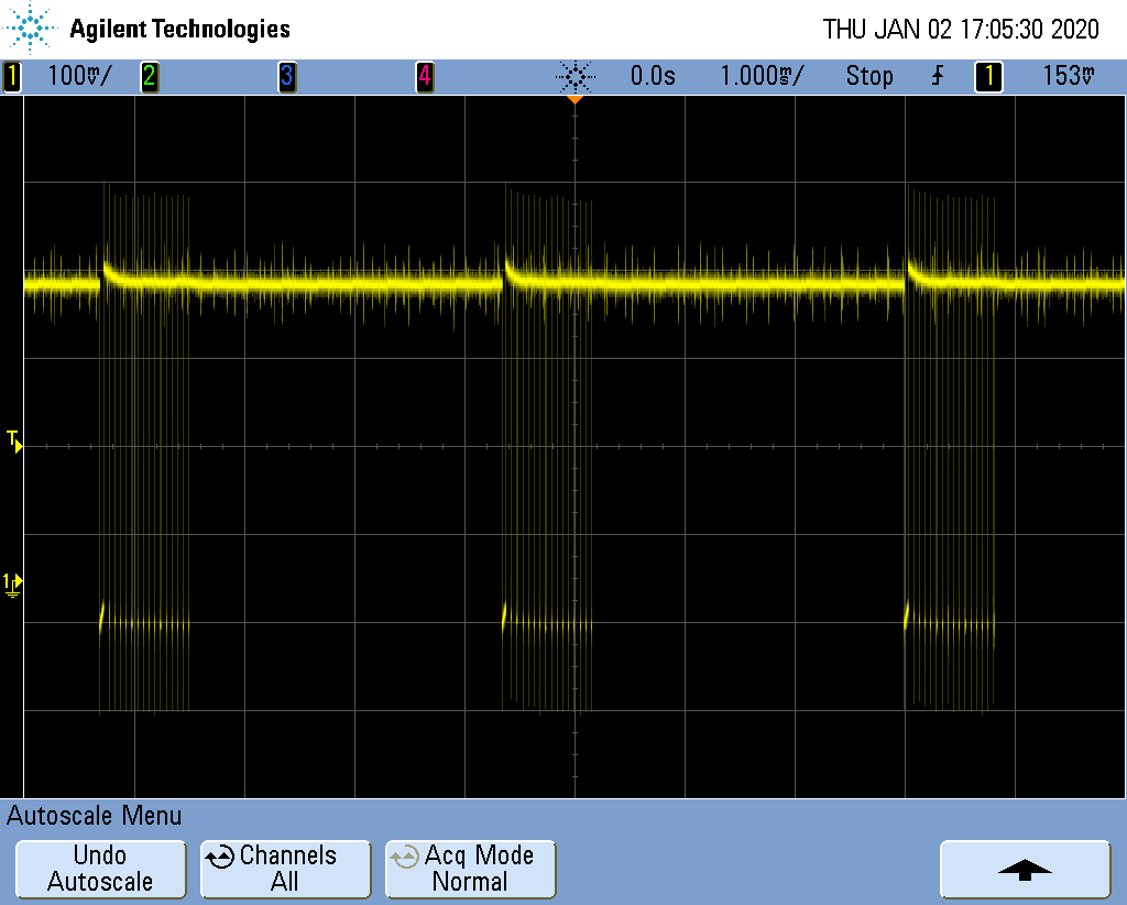
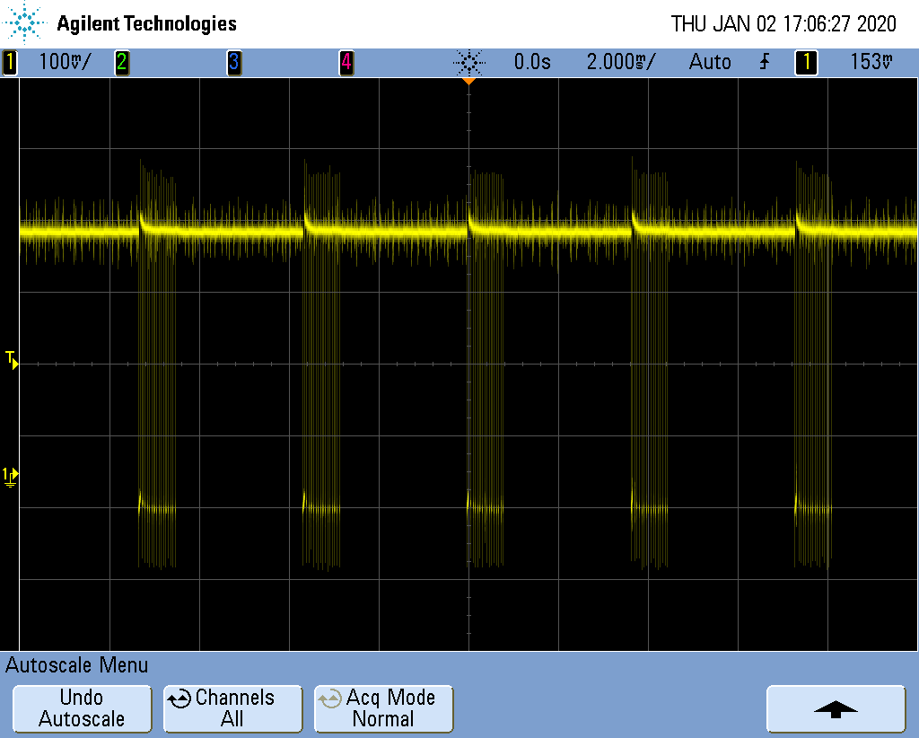
I have confirmed that SN65HVDA540 is getting inputs from 1443 with oscilloscope till board goes into BUSoff state, but at output side there is constant voltage which means nothing in CAN's language.I checked hardware side too. Everything is fine. So I doubt that may be SN65HVDA540 IC is not responding.
Is there anything like SN65HVDA540 goes into sleep mode due to some reasons and then never responds?
Is there way to trigger IC to make it work? Is there any way by which I can say surely that IC is not responding properly?
IC is actually made for harsh environment. So there is very less possibility of IC dying.
I even went through datasheet of SN65HVDA540, but didn't get much useful information that can help in debugging.

Regards,
Rajeshwari

  • Hey Rajeshwari,

    I've assigned one of our CAN experts to this thread though with the holidays in the US, response may be a little delayed.

    In the mean time:

    1) Can you provide a schematic around the device?

    2) Waveforms of your inputs/outputs?

    3) Any kind of testing done on the device prior to it not working (temperature testing or qualification testing?)

    4) Have you tried desoldering the unit and soldering a new one to verify that the original IC was damaged?

    5) Are you only seeing one unit fail?

    Thanks,

    -Bobby

  • Hello Bobby,

    1) Can you provide a schematic around the device?

    1443 detects certain gestures and sends corresponding result over CAN which are currently being received in Canoe software. 

    2) Waveforms of your inputs/outputs?

    Currently I do not have screenshots. I will post them soon. But I checked input to IC(txd an rxd) with autoBusOnEnable=1, it is showing data. On other side, i.e. at pins CANH and CANL it is showing constant DC voltage. 

    3) Any kind of testing done on the device prior to it not working (temperature testing or qualification testing?)

    Nothing unusual. Simply results of gestures where being sent on CAN.

    4) Have you tried desoldering the unit and soldering a new one to verify that the original IC was damaged?

    We didn't try it actually. Currently we don't have new IC. We are thinking of this option, but before that we need to be sure that IC is faulty. Because it was working fine and IC is made for harsh environment, so there are very less chances of failure of IC.

    5) Are you only seeing one unit fail?

    Yes. Only CAN part is not working. Other things are working fine as expected.

    Thank you,
    Rajeshwari

  • Rajeshwari,

    When you say constant voltage on the CANH and CANL pins, what voltage is that? My first thought was that the device is going into standby mode for some reason, but if the CANH and CANL pins are at a recessive level, this isn't the case. You said that there is data on RXD, or just data going into TXD and then the CAN bus is not responding?

    When you get screenshots of the CAN bus, can you get screenshots of the bus while it is working correctly as well as when it is not functioning correctly?

    Regards,

  • Hi,

    Constant voltage on the CANH and CANL pins is 2.41V with respect to ground provided busoff state is reached.

    You said that there is data on RXD, or just data going into TXD and then the CAN bus is not responding?
    When I try to send CAN message to the board, ack error is observed on transmitting side. And in 1443 receive interrupt is enabled which calls this 'DCANAppCallback' callback on interrupt. But this callback is not getting called. 
    In our application board continuously sends CAN message. And as board is reaching to busoff state I turned on autoBusOnEnable. So CAN will try to send continuous message on bus and then I observed TXD pin of SN65HVDA540 IC which showed continuous data frames. 

    When you get screenshots of the CAN bus, can you get screenshots of the bus while it is working correctly as well as when it is not functioning correctly?
    This is not possible as CAN communication is off. 

    Thanks,
    Rajeshwari

  • Hi Rajeshwari,

    A constant output voltage during a bus off condition is expected (since at this point TXD will generally remain high as well).  Can you confirm that the CANH/CANL voltage remained at ~2.4 V even before the bus off condition was reached (i.e., when TXD was still toggling)?

    If CANH/CANL do not toggle in response to TXD at all, then there could be a hardware fault related to the TXD connection (i.e., the pin is stuck high, stuck low, or left disconnected/open) or an issue with one of the power supplies (VCC or VIO) - could you please check these items?

    If CANH/CANL are only observed to be at a static level during a bus off condition, it is possible that they were toggling prior to the bus-off but with poor enough signal integrity that the CAN bus's frame error rate was too high for operation.  If that were the case, we should look into the signal integrity of the CAN lines.  Will you please let us know the data rate used, how termination is implemented on the bus, and what other components may connect to the CAN bus (e.g., other nodes/cabling as well as things like common mode chokes, filtering capacitors, etc.)?  It should also be possible to capture CANH/CANL waveforms if auto bus on is enabled and TXD toggles.

    It would also be good to double-check the state of the STB pin, although from what you describe it sounds like the device is in normal mode (since the CANH/CANL voltages would be weakly biased to 0 V in standby mode rather than the recessive level you are observing).

    Regards,
    Max

  • Hi,

    For continuous toggling data at TXD pin of IC I made 

    dcanCfgParams->autoBusOnEnable = 1;

    After that I am getting toggling data on TXD pin. But weird thing that I observed at TXD pin is even if I change data that is being send on CAN bus in code, data frame observed at TXD remains same.I am attaching screenshots for the same.


    About termination, I am just using CANH and CANL pins from board, connecting them to DB9 connector with 120ohm resistor, so that we can receive CAN message on receiving side.

    Voltage values at different pins when device is in running mode:

    TXD:      3.25
    GND:     checked continuity with board's ground. It's fine.
    VCC:     4.91
    RXD:     3.31
    STB:      0.038
    CANH:   2.43
    CANL:    2.43
    VIO:       3.312

    CANH/CANL voltage are at ~2.4 V even before the bus off condition was reached. 

    STB pin is at ~0V, so we can say device is in normal mode itself.

    Thanks,
    Rajeshwari


  • While taking above screenshots, I am sending continuously varying data over CAN.

  • Hello team,

    Any update on my query?

    Regards,
    Rajeshwari 

  • Rajeshwari,

    Thanks for your patience on this. In your oscilloscope shots, it looks like your controller is sending error frames over and over as a result of the RXD not matching what is sent on the TXD. It then repeats this same process because you have configured it to auto repeat the message. If your CANH and CANL signals are not being produced at all, then this makes sense as the RXD is mirroring what is on the CAN bus.

    Is it possible to get TXD and CANH and CANL on the same oscilloscope screenshot while sending data on TXD? If the device is not in standby mode, the only other reason TXD would not be driving the CAN bus is some kind of damage internally. Has this happened on more than one device?

    Regards,

  • Hi,

    Actually there is constant voltage at RXD(~3.31), CANH(~2.41) and CANL(~2.41) pin. 

    At STB pin shows ~0.038, can I assume device is in normal mode?
    I even tried reseting AR_GPIO_0 pin through code so that transceiver will be in normal mode, but it didn't work.

    Currently, I have tried on single board.

    Regards,
    Rajeshwari 

  • Correct, with the STB pin voltage below 30% of VIO you will be in normal mode.  From what you are describing it sounds like the device is in normal mode with a recessive output.  Some possible explanations are:

    1. There is an issue with the connection to the TXD pin of the IC, either due to a PCB issue like a cold solder joint or with a device-related issue like an intermittent bond wire connections.  You could diagnose this by performing continuity checks on the PCB, by probing the TXD pin directly for a toggling signal, and by trying to replace the IC with a new one (if a valid TXD waveform is observed at the pin directly).

    2. There is an issue on the CAN bus such as a short between CANH and CANL lines preventing the bus from becoming dominant (>900 mV differential).  This causes the controller to try to transmit a frame, flag an error, re-try transmission, see the same error, and eventually go bus off.  During this time the TXD pin state will mostly be high (recessive), so unless the CANH/CANL voltages were measured during one of the short periods where TXD is confirmed to be low then it may be hard to diagnose the issue (unless there is a gross issue which could be diagnosed via impedance measurements, visual inspection, etc.).

    Can you please check these two items?  In my thinking they would be the most likely root causes.  If neither matches the issue, though, we can brainstorm on further possibilities.

    Regards,
    Max

  • Hi,

    I changed transceiver IC. And now CAN communication is working.

    Thank you very much all for support!

    Regards,

    Rajeshwari

  • Rajeshwari,

    That is good to hear. Please don't hesitate to let us know if some other issues occur in your application. I am now going to close this thread.

    Regards,