This thread has been locked.

If you have a related question, please click the "Ask a related question" button in the top right corner. The newly created question will be automatically linked to this question.

SN65LBC176-Q1: For 1PPS(1Hz) signal

Part Number: SN65LBC176-Q1

Dear Team,

Can SN65LBC176QDRQ1 transmit 1PPS(1Hz) signal as below waveform?

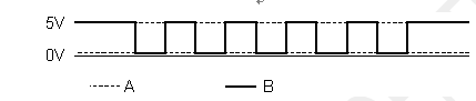
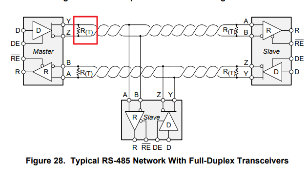
If the customer use RS485 interface, is 1PPS_CH1_P &  1PPS_CH1_N need an RT resistor?

BR

Kevin

  • Hi Kevin,

    Generally, this should be OK.  Please note that the "A" and "B" signals will not fully reach 5 V for the high level or 0 V for the low level, though, and so if there is a more specific definition available for the voltage ranges you may want to double-check that in more detail.  I wouldn't expect termination to be needed for such a low signaling rate.  I'd recommend testing without a termination resistance first and checking to verify that the signal integrity is adequate.  If you do include termination, not that it would reduce the voltage amplitudes on the bus (due to increased load current through the driver output causing additional voltage drops).

    Regards,
    Max

  • Dear Max,

    Thanks for the input.

    I will suggest to test it without Rt resistor between A and B

    So if we pull up to 5V, the signal at the output side still won't be 5V, right?

    BR

    Kevin

  • Kevin,

    Assuming no termination, using an external pull-up would help the high-level voltage get close to 5 V and using an external pull-down would help the low-level voltage get close to 0 V.  You wouldn't be able to get both benefits (pull-up and pull-down) on a single line, though.  For example, the schematic you shared has a pull-up only on A and a pull-down only on B.

    Max

  • Dear Max,

    Thanks for the input.

    What will be the suggested resistor value for termination? (maybe 100ohm?

    Can I use 0402 package resistor as place holder here?

    BR

    Kevin

  • Hi Kevin,

    Termination resistances values should be matched as closely as possible to the expected differential characteristic impedance of the transmission line, which is commonly either 100 Ohms or 120 Ohms.  You would want to make sure that the resistor is sized appropriately to handle the expected power dissipation (you should assume a few Volts of differential signal amplitude across it).

    Note that if termination is included, you would likely want to bypass the series 100-Ohm resistances.  Otherwise, these will form a voltage divider and attenuate the signal.

    Regards,
    Max