This thread has been locked.

If you have a related question, please click the "Ask a related question" button in the top right corner. The newly created question will be automatically linked to this question.

TUSB1210: TUSB1210BRHBT

Part Number: TUSB1210

Hi,

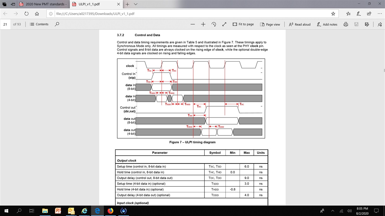
I couldn't find timing waveform of USB interface for clock in and clock out mode with respect to setup and holdup measurements. Does setup and holdup time timings measured at same clock edge when data out or at next clock cycle rising edge, please kindly advise.

Regards

Ranga

  • Dear Brian Zhou,

    Thank You for sharing the Timing Diagram which helps me to perform the timing analysis.

    I have one more question relating to same device. VBUS is connected to external supply for ULPI input clock mode and connected directly to USB connector in ULPI output clock mode as per the application diagrams shown in datasheet. Do we need follow to same connections in our design? Please kindly confirm.

    Regards

    Ranga

  • Dear Brian Zhou,

    Sorry, I miss to add one more question, I will consider timing parameters mentioned in datasheet only, I will ignore the timing details mentioned in timing waveform snap shot which has shared by you in previous thread.

    Regards

    Ranga

  • Dear Brian Zhou,

    Sorry for asking more details on timing waveform, Could you please help me to understand whether setup and hold timing is measured at same clock edge (where data out occurs) or next clock rising edge at receiving end. I saw some application notes in websites time for some devices setup time is measured at next clock rising edge however hold time is measured at same clock rising edge hence I got confused. Please kindly advise.

    Regards

    Ranga

  • 1: for vbus connection, if ofr host or OTG, a Vbus switch is needed ot control Vbus.

    2: for setup/hold time, you can measure at different clock edge. during measurement, you will moving the data at each edge until finding the setup or hold time it failed