This thread has been locked.

If you have a related question, please click the "Ask a related question" button in the top right corner. The newly created question will be automatically linked to this question.

TRS3221E: Signal logic on TRS3221 and THVD1451

Part Number: TRS3221E

Hello TI interface team!

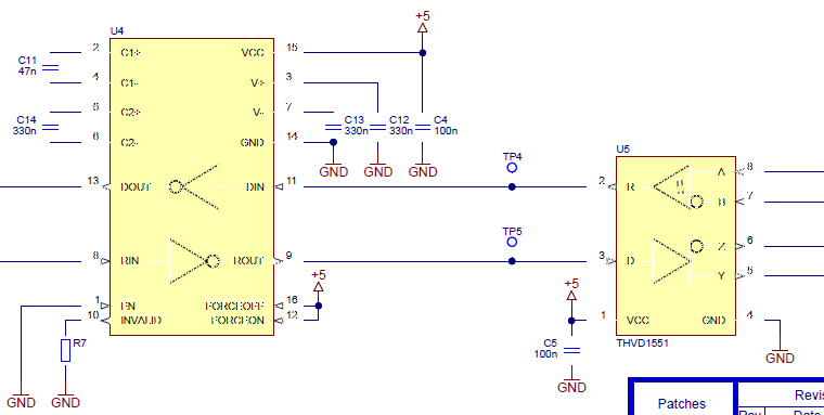
I have to make up a interface adaptor containing, among other parts, a RS232 <-> RS422 conversion.

For those I have selected the abovementioned components. They are directly coupled back-to-back by their logic-side signals.

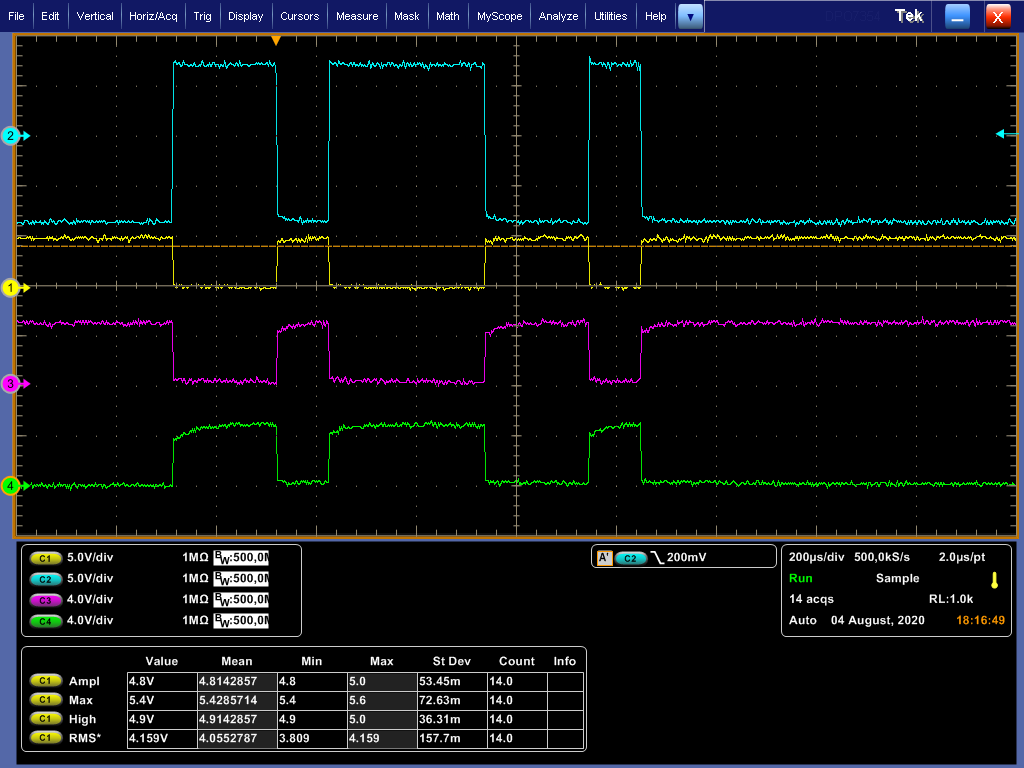
While I can see interface activity on both sides, the devices do not talk to each other.

Would I have needed to invert the data signals between the two ICs?

  • Hi Martin,

    I don't think you would need to invert the polarity of the signals (i.e., "high" and "low" bit values), but you should be careful to make sure that each transmitter connects to a receiver (rather than another transmitter) - this is sometimes confusing for RS-232 and can require use of a cross-over cable to swap TX/RX lines in some cases (depending on the connector pin assignments on each side).

    Do the devices on both the RS-232 and RS-485 recognize the same data protocol?  I.e., are they configured for the same baud rate and UART word/frame structure (number of start/stop/data/parity bits)?  I ask because the physical layer conversion is just one aspect of ensuring communication between these two different devices.

    If the data protocols are consistent and you think this is a hardware issue, then it would probably be helpful if we could review a schematic of the implementation as well as the recorded waveforms at both interfaces to see if any issues can be identified.

    Regards,
    Max

  • Hello Mr. Robertson!

    I already know a bit more and can provide some data.

    I can see the loopback from the RS422 side, but that could still mean I have both sides wrong.

    Enclosed is a circuit excerpt and a waveform for letter 'b'.

    Trace 2 is RS-232, Trace 1 is TTL at TP5, Trace 3 is Tx+ and Trace 4 is Tx-

  • Hello,

    This data path seems to be working properly to me.  A negative voltage on RIN corresponds to a logic-high signal on ROUT (RS-232 uses inverse logic, so this is correct), and the logic-high signal applied to the "D" pin of the RS-422 transceiver results in a positive differential output.  Similarly, the positive input on RIN corresponds to a logic "low" which is represented by a negative differential output from the RS-422 transceiver.

    However, after checking the RS-422 standard I am not so confident in the correct polarity:

    The RS-232 standard defines the following states:

     - Negative interchange voltage = binary state "1" = signal condition "mark"

     - Positive interchange voltage = binary state "0" = signal condition "space"

    (This is what I meant above when I referred to inverse logic.)

    Now, looking at RS-422 I see something similar:

     - "mark" condition = binary state "1" = negative differential voltage (Vob > Voa)

     - "space" condition = binary state "0" = positive differential voltage (Voa > Vob)

    Based on this, you may want to experiment with swapping the RS-422 signal wires or checking more into the signal polarity expected from your target device.  From what I've seen, though, many products do not seem to follow the polarity as defined in the TIA-422 standard.  My impression is that the inverse of this has become a kind of de-facto implementation.  (I know of a similar situation for the RS-485 standard versus its actual usage.)

    Max

  • Thank you very much for the vindication of my results. It is the problem that I do not have anyone else here who does posess some knowledge about such matters, so it happens that one becomes unsure about the most basic things!