This thread has been locked.

If you have a related question, please click the "Ask a related question" button in the top right corner. The newly created question will be automatically linked to this question.

SN65HVD888:Power over bus communication evaluation

Part Number: SN65HVD888
Other Parts Discussed in Thread: TIDA-00527, THVD8000, SN65HVD3082E

Hi

We want to use Power over bus solution as the connection between Wire remote controller on the HVAC system. Current, we are evaluating the use of SN65HVD888 chip to achieve this function

we had PCB sample to do some test.
And ,we have some reference  like TIDA-00527 and some E2E support forums reference .

Test condition:(The bus has not assembly 120 ohm terminal )(The data used Manchester code )  (Baud rate: 115200 bps)

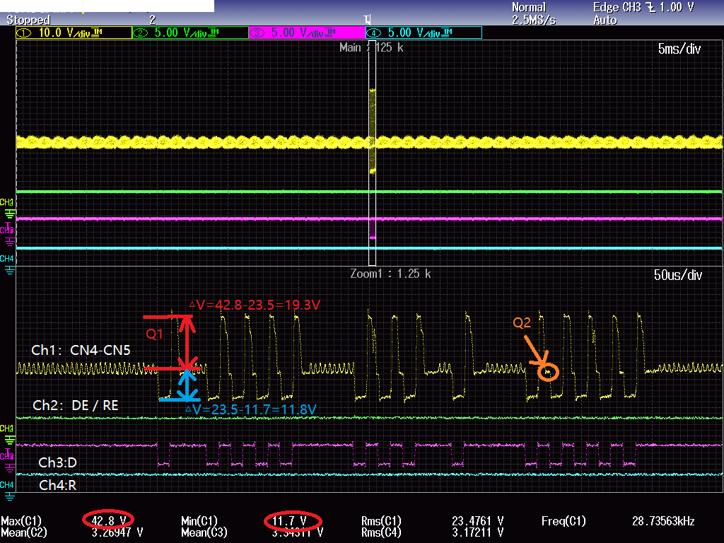
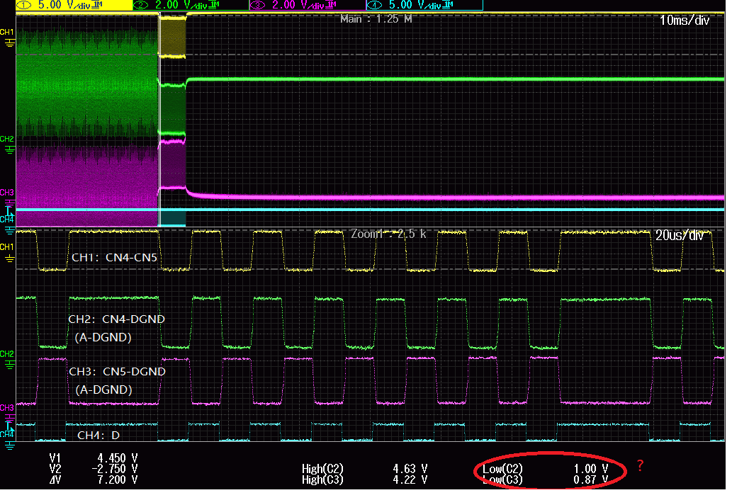
I have some question about the wave Ch1(CN4 - CN5) . Hope to get your support. 

① Why is the waveform of channel 1 not symmetrical at 24V, and offset up and down by ±5V ? Did we miss any design requirements ?  

② There are step on the positive signal to  negative. I don't know why this step exist ?    Show Q2 indicator in the below picture .

1. Schematic & Test wave

 Best Regards

Ethan Lu

Aug / 07 / 2020

  • 1. Schematic & Test wave 

  • Ethan,

    First of all, I would like to let you know that TI has pre-released a power over bus transceiver THVD8000. The theme is similar to TIDA-00527 however the modulation is integrated so the implementation should be much easier.

    Back to your questions. I don't think the bus differential voltage can exceed the RS485's Vod. Can you start by testing the data communication then adding the power delivery components? I'm also curious the reason you choose SN65HVD888. I guess it's related to its polarity free feature. In this setup, the polarity is generated by the pull up/down at each local node.

    Regards,

    Hao    

  • Hi Hao:

    Thanks for your quick reply. The IC SN65HVD888 was choice is our other project was used . I mean it's same as chip on the indoor controller . In order to keep same chip choice as indoor controller design.

    I test the data communication without power over bus follow your suggestion.

    ①It looks good except the low level voltage is  a litter high on the pin A B to GND . Could you confirm it is OK?

    ②Back to my first question before, Could you continue give me some valuable suggestion?

    Test condition (1. remove power on bus component  )

    Ch1:CN4-CN5    ;      Ch2:CN4-DGND (A-DGND)       ;         Ch3:CN5-DGND (B-DGND)             ;            Ch4:D


  • Ethan,

    Again I suggest you consider testing with THVD8000, whose samples and EVMs are available on ti.com. Although I don't know the design goal, I think the system implementation should be much easier with THVD8000 down the road.

    I think the difference on the voltage level (maybe also on the amplitude?) is due to the asymmetry between A/B lines. Could you test with the power function but leaving the series inductor (L10 and L7-2) out? A tip for debugging is to compare the bus voltage at the A/B pins with the bus voltage (CN4/CN5).

    Regards,

    Hao

  • Hi Hao:

    Sorry about delay reply this topic . 

    Current, I  have no conditions to do this test with THVD8000 . But now I want to use this IC ( SN65HVD888 )  to realize this function. I meet some problem as before described.

    I summarized the test wave into excel file .  

    RS485 communication issue-20200819.xlsx

    I have three question for you.

    ① I think the wave is abnormal  . What do you think?

    ② What factor result in this problem?

    ③ For this design, I don't understand why this is such a waveform. I need to solve this problem.Could you give me debug guidance?

    By the way , Can I have your email ?  I want to communication with email with you. This may be convenience for me .

    Best Regards

    Ethan Lu

  • Ethan,

    Thanks for your data. Yes, the waveforms are abnormal. The overshoot looks like due to the inductive loading. Can you reduce 3.3mH with a smaller value? What's the supply source impedance? Can you capture the 24VDC supply waveforms with and without load? Similarly can you test the power over RS485 with and without load? Another experiment would be testing with a different transceiver like SN65HVD3082E?

    Again THVD8000 is pin 2 pin with common RS485. It's straightforward to replace SN65HVD888 by THVD8000 or replace the TIDA board by the THVD8000 EVM (with L/C). My email is hliu @ ti dot com.

    Regards,

    Hao