This thread has been locked.

If you have a related question, please click the "Ask a related question" button in the top right corner. The newly created question will be automatically linked to this question.

TL16C550D: Connecting with UAR

Part Number: TL16C550D

Hi All,


I have a question about the TL16C550D.

When connecting with UART only by transmitter, connect not used CDC/DSR/RI pin to GND or Open?
And RTS to CTS short circuit. Is it OK?

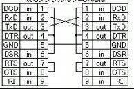
When connecting to RS232C, the following connections were made.
 - Short circuit RTS and CTS
 - Short circuitDTR and DSR with DCD
 - RI is open
Is it possible to process the pin in the same way as this?


Best Regards,
Ishiwata

  • Hi Ishiwata-san,

    "connect not used CDC/DSR/RI pin to GND or Open?"

    As a general rule thumb, inputs should never be left open as this could cause them to float to a mid rail value. Most inputs these days use CMOS structures which would cause shoot through currents, this would result in higher supply current and in rare cases, could damage the device over very long periods of time. I would use a resistor to set them to either pulled to Vcc or GND. (Incase you want to depopulate the resistor and re-bias the pin later on)

    "And RTS to CTS short circuit. Is it OK?"

    I would probably do this with a low series resistor to short those two, incase you may need to unshort them later.

    "When connecting to RS232C, the following connections were made.
     - Short circuit RTS and CTS
     - Short circuitDTR and DSR with DCD
     - RI is open
    Is it possible to process the pin in the same way as this?"

    Yes, this should be possible. This looks like a null modem set up (usually done through cabling).

    RI should be biased either HIGH (Vcc) or LOW (GND) to prevent shoot through currents (same explanation as above). I would personally do it with a 4.7k or 10k resistor.

    -Bobby

  • Hi Bobby-san,


    Thank you for your reply and support.

    1. Is it possible to perform UART transmission/receiver communication with the connection shown below?

       I think that communication is not possible unless RTS and CTS are short circuit as shown in the figure. 
       CTS-RTS is short circuit in Fig.1 of the datasheet.


    2. If DTR-DSR-DCD and RTS-CTS do not require a short circuit, pullup or pulldown may be used.
        DTR and RTS are an output pin, so I think that there is no problem with Open. Is this correct?
        (I understand that RI is 4.7k to 10k and pullup or pulldown is recommended.)

    Best Regards,
    Ishiwata

  • Ishiwata-san,

    Bobby is out of the office at the moment so I will try to help.  The connections that you show are not uncommon and will work in most cases.  Typically, though, for systems implementing hardware-based flow control the RTS/CTS lines are used so that the RX FIFOs do not overflow in the event that they are read more slowly than they are written.  This is what is shown in Figure 1.  The receiving device asserts RTS when it has room in the FIFO to accommodate data, and the corresponding transmitter uses this as indication that it can send serial data from its TX FIFO.  Looping back CTS/RTS within a system gets rid of this benefit, and if there is a case where there is a disparity between read and write speeds at each end of the communication link then it is possible for FIFO overruns to occur.  So, you should be sure either that the system can tolerate these overruns, that they could be avoided by reading the RX FIFO fast enough, or that flow control is implemented via software rather than hardware.

    Regards,
    Max

  • Hi MAX-san,

    I apologize for the late reply.
    Thank you for your support.

    Best Regards,
    Ishiwata