This thread has been locked.

If you have a related question, please click the "Ask a related question" button in the top right corner. The newly created question will be automatically linked to this question.

DP83630: Guidance on PTP Implementation

Part Number: DP83630
Other Parts Discussed in Thread: DP83640, TIDA-00496, CDCE913

Hi Team,

My customer is looking to implement a slave PTP device with a single DP83630 connected to an NXP S32K microcontroller as a MAC and some questions have come up around clocking for their specific use-case.

The current idea is to use a third-party PTP master (that is synced to the GPS PPS pulse) and sync the clocks for all computer and sensor nodes (incl this PHY/MCU) in their system and time stamp their ethernet packets. Alternatively there’s another TI app note that talks about "synchronizing a DP83640 PTP master to a GPS receiver". This could also work- figure 1 in that doc shows GPS PPS output connected to the DP83640 (or presumably, -30 as well), in which case, they wouldn't need a stand-alone PTP grandmaster, perhaps DP83630 could do this function. 

Our concern with this approach is that a controller needs to be connected directly to both DP83630 & GPS unit, which the customer cannot do (GPS unit has no interface to this PHY/MCU board), but rather the controller (S32K MCU) could talk to the GPS thru its DP83630 PHY ethernet connection which connects upstream to the same network switch as the GPS unit.

Does any of this make sense and is it doable? We are just looking for some guidance here.

Thanks,
Mitchell

  • Hi,

    DP83630 as Master needs a reference clock to which it can run the Time Stamping enginer and generate the Time sync Packets.

    It can take 1 pps GPS signal and local 25 MHz and synchronise the Time Stamp engine or a 25 Mhz Synchronised clock. From GPS unit can be connected to Host while providing 1 pps to DP83630.

    Regards,
    Geet

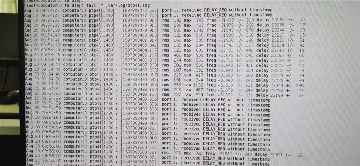
  • 在ptp4l.log里显示

    port 1:received DELAY_REO without timestamp

  • You need to review the configuration on the Slave.

    Regards,

    Geet

  • Thank you for the answers. The follow up questions I have are:
    Which of the three clock options listed in the reference design (TIDA-00496, shown below) should I use for the 25MHz reference in PTP master mode? It's not clear to me what's the advantage of any of them, particularly the X1 vs. Y2 crystal oscillators:
    - CDCE913 (VCXO) + 25MHz crystal (Y1 + U3 in ref design) - and who controls the VCXO?
    - 25MHz crystal (is this Y2 in ref design?)
    - Oscillator (is this X1 in ref design?) 
    Another question is about syncing to PPS: per TI app note SNOA549A, there are two ways to do this:
    1. Use "clock reference that is independent of the GPS 10MHz receiver clock", as discussed in section 2.1, "Pulse-Per-Second Sync",
    or
    2. Use "direct reference connection discussed in section 2.2. 
    I don't have the 10MHz out of my GPS receiver (Applanix LVX), so this solution is out.
    Section 2.1, step 2 says to conf the GPIO as an event monitor for PPS; does it matter to which GPIO [1,2,3,4,8,9] pin is PPS connected to?
    Section 2.1, step 3.b says to read the time from the GPS; is GPS receiver RS232 NMEA datastring appropriate input, and on what IOs on the PHY?
    Section 2.1, step 3.c says to "calculate the diff between GPS time & PTP time and use a step adjustment to correct PTP time".. where is this done, inside PHY, I assume, and is that IP provided with PHY firmware?
    Sorry for the many questions, but I'm just trying to get this right the first time; if there's another doc that I should read about this, please let me know.
    Many thanks,
    Oliver C. Colic
    Senior Hardware Electrical Engineer
    Embark Trucks
    +1-765-714-2622
  • Hi Oliver,

    1.  Clocks : This is driven by the applications need. Please refer to below app note on key aspect to use any of them. 

    https://www.ti.com/lit/an/snoa548a/snoa548a.pdf

    2.1  Yes, you can choose one of the IO. You to program PTP TIme Stamp engine accorindgly to latch the input.

    2.2 This has to be read by SOC running the PTP engine to sychronise the PTP counter with GPS counter. You may need to check with your GPS module vendor on exact NMEA command.

    2.3  This has to be done in PTP module.

    2.4 You may want to refer to Software integration guide as part of the Software Driver zip folder. It has detailed instruction on steps involved for driver integration.

    Regards,

    Geet

  • Thanks for the reply Geet; however, I didn't really understand the answers - here's what I sitll don't get:
    - Which of the 3 clock options should I use? I already read the SNOA548A doc that you recommended, and if I select PPS sync method (section 2.1), there is still the question of which of the two crystals (X1 or Y2) to use? Is VCXO+XTAL only useful if using the direct reference sync (sect. 2.2)? None of this is directly discussed in that doc.
    - Where to connect the PPS input and how to configure the PHY to sync on it: Based on your advice, per SW Dev Guide, I think we can set bits in PTP_EVNT register to enable event monitoring for PPS input. I'm assuming what you called "PTP Time Stamping engine" is what the sw dev guide calls "Event Timestamp Unit" (section 3.1.5.1)? 
    - How does the PHY read the time from GPS unit? Should I provide NMEA data from GPS to PHY, and on what pins? Your answer about "SOC running on the PTP engine" does not make sense to me - not sure what that means.
    If you don't mind, could you give me a quick call at 765-714-2622 anytime 9am-9pm pacific time?
    Thank you kindly,
    Oliver Colic.
  • Which of the 3 clock options should I use? I already read the SNOA548A doc that you recommended, and if I select PPS sync method (section 2.1), there is still the question of which of the two crystals (X1 or Y2) to use? Is VCXO+XTAL only useful if using the direct reference sync (sect. 2.2)? None of this is directly discussed in that doc.

    - You can use XTAL ( 25 MHz) to clock the DP83640 and GPS PPS to GPIO of the PHY.  You need to configure the GPIO as Event capture, PHY on every 1 pps, will raise interrupt and will store the time stamp counter in register. For the same time stamp, application has to read the GPS counter ( if your application needs to have knowledge of the Time of Day as well) and adjust the DP83630 counter.

    Where to connect the PPS input and how to configure the PHY to sync on it: Based on your advice, per SW Dev Guide, I think we can set bits in PTP_EVNT register to enable event monitoring for PPS input. I'm assuming what you called "PTP Time Stamping engine" is what the sw dev guide calls "Event Timestamp Unit" (section 3.1.5.1)?  This is correct.


     How does the PHY read the time from GPS unit? Should I provide NMEA data from GPS to PHY, and on what pins? Your answer about "SOC running on the PTP engine" does not make sense to me - not sure what that means.

    PHY does not co-ordinate directly with GPS unit. MCU running gPTP has to co-orindate and adjust the Time Stamp counter to GPS time.

    Regards,

    Geet