This thread has been locked.

If you have a related question, please click the "Ask a related question" button in the top right corner. The newly created question will be automatically linked to this question.

SN65HVD230: Can driver not working properly

Part Number: SN65HVD230
Other Parts Discussed in Thread: TCAN332

Hello, 

I am struggling to use the Can driver with an STM32: I purchased a board with just the driver and two resistors.

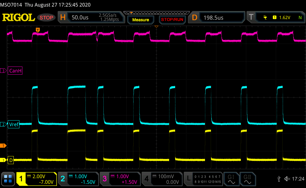
At 1Mbps the Vref collapses and the canbus doesn't even move.

I replaced with a short the slope compensation resistor, added 100nF + 10uF decoupling capacitors but still nothing; furthermore I am measuring 20kohm resistance between Vref and D pins, is that normal?

P.S. I tried with a TCAN332 and that works flawlessly, so the rest of the circuit must be ok.

Could this be a grey market IC?

I've attached a scope screen-shoot and a picture of the IC.

  • Hi Marco,

    What's the last line of the top-side marking - does it say "ACNP"?  (I'm struggling to resolve that first character.)  If so I'm not sure that's a valid code - when I look it up it maps to a different device.  I can double-check with our Quality team but I wanted to confirm the code first.

    Have you by chance tried swapping out the IC with a new sample (one from ti.com or from an authorized distributor)?  I ask that because of the lot trace code issue and because I don't think that 20 kOhms of leakage from D to VREF is expected; these are independent circuits.  (The resistance measurement was performed with the IC powered off and no other voltages applied, correct?)

    Is VREF connected to anything on the PCB?  It doesn't look like it since there is just a single 120-Ohm termination resistance.

    Is anything going on with VCC - i.e., does it dip at the same time as VREF? I initially suspected that the additional ICC during a dominant output state may be pulling the VCC down (e.g., if the regulator couldn't source enough current), although the addition of decoupling capacitance should have helped a little and generally I would have expected similar behavior from TCAN33x if this were the case.

    You mentioned that the CAN bus is totally flat at 1 Mbps - is it operational at any data rate?

    And, just to be totally sure - the "CTX" net corresponds to the TX output of the MCU and the "D" input to the transceiver, while "CRX" corresponds to the "R" output of the transceiver and the RX input to the MCU, correct?

    Max

  • Hi Max,

    yes it is "ACNP" and then a little and undelined "G4"

    I don't have available an original one for now however, because I purchased 3 boards, I've tested a second one and they both behave the same way. Yes, I measure the resistance with no power and also lifting the 2 pins, just in case.

    Vref is not connected to anything, it's just a pad with no tracks.

    VCC is stable, a bit of HF glitches during transitions but the decoupling caps I've added will fiter that, it might also be noise. It is very similar to the spikes visible on the canH signal

    Yesterday I took a measurement for 100kbps, now CanH changes state, however Vref collapses completely; that is what makes me believe that the IC might be counterfeit.

    Yes, I mapped the pins like you said, TX from MCU to pin D (1) of the driver.

    Regards,

    Marco

  • My issue seems similar to this one and this one,

    and the solutions were to replace the IC.

    Could it be a problematic batch?

    Regards,

    Marco

  • Marco,

    I don't think it is a problematic batch.  This sort of issue would have been detected by our production test, which verifies device functionality and parametric performance per the datasheet limits.  I also checked with our quality team and we've had no known test escapes/quality excursions and field returns have been minimal (and been root-caused to overstresses).  It is possible that the unit was damaged somehow after shipping.

    I'm still a little concerned about the possibility of being a counterfeit IC, though.  Looking deeper into the topic, the markings indicate that the device was assembled either in 2018 or 2008.  I couldn't trace data as far back as 2008, but it is not a valid 2018 code.  And, we were able to look at photos of devices produced in both 2008 and 2018 at the listed assembly site and they have different top-side silk appearance (fonts/logo/etc.).

    Given the doubt, I think if you could test with a known-good IC ordered from TI it would be best.  You may want to let the PCB supplier know about this so they can check their supply chain (and work with us as needed on counterfeit validation).

    Max

  • Hi Max,

    I found a different board, similar PCB but different IC and now it's working properly, confirming that the IC was the problem.

    I took a picture of both, for reference. Even the TI logo is quite different:

    Thank you for the support.

    Regards,

    Marco