This thread has been locked.

If you have a related question, please click the "Ask a related question" button in the top right corner. The newly created question will be automatically linked to this question.

SN65HVD232: The communication failed

Part Number: SN65HVD232
Other Parts Discussed in Thread: SN65HVD256

Hi Experts:

My customer is using the SN65HVD232 and SN65HVD256 in their system for the communication between the boards. Now there is small probability to be failed connection, could you please help me to check the schematic if any potential risk , and i will do more investigation then.

  • Hi Jason,

    A quick look over the schematics doesn't indicate any major issues. I see two places where 120-ohm termination is used, chokes on stub nodes, and power and decoupling is setup correctly.

    It appears that the second figure has a switch for selectable termination. If this is active at the same time that two other nodes have included termination, then the load from the excessive termination may be too great for stable communication. Can you confirm that this switch is disabled and only the two ~120-ohm termination points exist on the bus during the testing? 

    If it is possible to capture scope shots of the CANH and CANL lines (TX and RX lines are also very helpful if enough probes are available), these would help identify where an issue may be occuring based on the noise level, voltage level, and symmetry of the signal lines. Would it be possible to grab scope shots of a test where connection failed?

    Let me know if there are other developments or if you find a suspected cause for the failure.

    Regards,
    Eric Schott

  • Hi  Eric:

    Thanks for your comments , i will reply if i collected more information .

  • Hi Eric:

    the switch is disabled and only two 120 ohm during the testing. In this design , the SN65HVD232 is working with SN65HVD256, could them work together? 

    Now we captured the waveform of the CANH/L for your reference.

    a) CANH/L differential waveform:  I seems that the high level is always changing , i don't know if it is the cause.

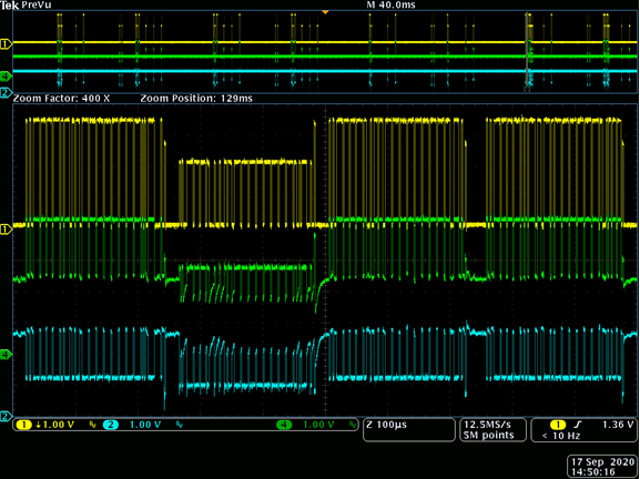
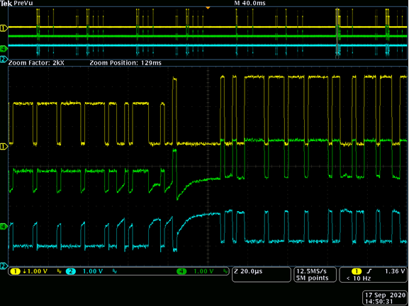
    b)  CANH (Ch4) , CANL(Ch2) ,  CANH-CAHL(Ch1)  


    Do you think the above waveform is reasonable or not ?  Customer want to save time to resolve this issue , could please list any checking points including the hardware and software ? They can do them at the same time.

  • Hi Jason, 

    Thank you for checking on my questions and sharing the scope shots, this is good information.

    a) CANH/L differential waveform:  I seems that the high level is always changing , i don't know if it is the cause.
    The different levels are likely the different transceivers driving the bus. The last dominant pulse in each sequence appears to be at a different level - this is the ACK bit which is driven by the receiving node(s). When probing a node, that node's signal is expected to appear stronger because it does not need to pass through the resistive elements of the cabling that connect remote nodes. 

    As far as signal integrity goes, the waveforms appear clean, symmetrical, and of sufficient magnitude- I wouldn't expect these waveforms to cause communication failure. If these shots are representative of all working conditions (no added noise, nodes, or other harness changes), I think it's unlikely that the sporadic failures are a hardware problem. 

    It's a bit trickier to debug the software portion as this can vary between system. The waveforms appear to be consistent with the CAN standard so unless a particular error is being reported by the controllers during the failure (e.g. a CRC error) it may be a higher-level issue. Could you share more information on what the communication failure entails? Is this reported by one or both nodes? What specifically does the reporting node report? Can communication be reestablished afterwords or does the system lock up?

    To further explore potential hardware possibilities, would it be possible to capture the state of the bus during a communication failure? This could potentially be done by triggering the scope when the failure is recognized through software or - how I would recommend - using a logic analyser which can recognize CAN logic connected to an RX pin in the system. Set the analyser to trigger the oscilloscope on a NACK so we can see the waveform that was invalid or unrecognized by the node. 

    If you get any partial information, feel free to share and I can comment to try to save time with the resolution. 

    Regards,
    Eric

  • Hi  Eric:

    Thanks for the detail comments. 

    This is the charging pile application, customer is just reported by the CAN failed from their terminal customer, i will get to know more about the situation which trigger the failure. 

    So if customer want check the issue in the software side , they could only check the CRC error ? 

  • Hi Jason,

    The CAN controller is responsible for interpreting CAN protocol and relaying information to a processor unit (sometimes CAN controllers are integrated into MCUs or similar devices). If the CAN controller recognises an error or breach in CAN protocol, it can report the nature of the error in software (one such type of error is a CRC error). Weather or not the software is able to interpret this error and its details or just recognises there was an error depends on the system. If such information is available from the customer's software, it would help identify where the source of the error is. Otherwise, we may have to look at the raw data and waveforms to determine what causes the failure. 

    Regards,
    Eric Schott