This thread has been locked.

If you have a related question, please click the "Ask a related question" button in the top right corner. The newly created question will be automatically linked to this question.

TL16C2552: Problems recieving fits byte after a frame sended.

Part Number: TL16C2552
Other Parts Discussed in Thread: TL16C450

Hi,

Recently we have change the DUART PC16552 of national to TL16c2552, Without code changes TL16c2252 seems work good, but one month ago we are starting with a problem that we don't understand.

After a frame sended, when we acces to read BRB in the first byte recieved, the data bus not works properly.

This is a capture with this problem:

Red -> CS

Yellow & green -> D2 & D3 (but this occurs with all bus)

On second byte of same frame and the rest works good.

What could be wrong?

We work on TL16C450 mode and after we recieve INT, we acces to LSR and when DR is 1 we read the BRB.

Thanks!

  • In addition of this issues, it's only occours when tl16c2552 is powered at 5Vdc and we are traying to recive and 0xFF data.

  • Hello,

    Can you provide a schematic for us to review?

    Can you also provide HIGH LEVEL code of your procedure of when you run into the problem?

    (How do you initialize the device?)

    (Clock speed?)

    Thanks,

    -Bobby

  • Hi Bobby,

    The eschematic is a simply connexcion between de UART and ATMEL AT80c51 at P0, the P0 is and open-drain I/O port and there is a pull-up to 5V. We have been searching any solution and it seems like the output of UART can't drive a FF character to and open-drain port because the oscilation in the ouput data bus of the UART appears in VCC too. 

  • Hi Bobby,

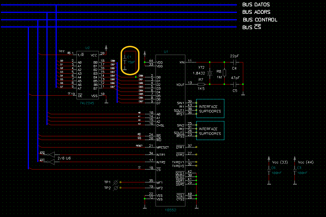
    We are trying to avoid that it seems noise, and we have founded a solution that we don't understant. To isolate the uart of other bus elements we have insert a buffer (74LC245) between CPU and UART, but it doesn't work.

    But if we instert a CAP in any bus pin the noise deseapers and all works fine.

    I atthache new shematic, and a capture of this noise without CAP1 and a capture of the same signals with CAP1 placed.

    Could be any Ground problem?

    No CAP1

    CAP1 Placed

  • Hello,

    If the Vcc rail is also seeing issues, it seems like maybe there is a problem with the power. Are you using some kind of switching regulator? Are you able to see how much current is being driven from the power when you see this issue? Since it pops up at 5V, I'm wondering is its due to high current causing the Vcc to collapse. It may also be that the Vcc is unstable (typically require a certain load cap on the output to stay regulated). 

    Also, In the schematic I don't see local decoupling on the Vcc pin of our device. 

    I would also recommend increasing the sampling points on the o-scope. currently you are using 2000pts of sampling. Typically I use between 10k to 100k pts of sampling to get a clearer resolution on the scope.

    -Bobby

  • Thanks Bobby for your help.

    Certanly It works with a switching regulator, but is a medical power supply (VLT110-4303), and before and after recieve the 0xFF there isn't any noise in VCC, it only occours at the moment UART put data on the data bus. If data is 0xE0 there isn't any problem in VCC.

    Thanks

  • I'm wondering if the issue may be due to the PCB layout. The pins looks like they slightly overshoot when the line goes HIGH. In the bad case, it looks like a mix between crosstalk (noise jumping to the parallel trace) and some kind of resonance. This may explain why the issue occurs at 5V (higher current means higher di/dt resulting in more oscillations). This would also explain why adding a cap would help (it would help to dampen the ringing).

    -Bobby

  • Hello Bobby,

    Thanks for your help!. We have been looking for any overshooting in data bus and we haven't seen any, about crosstalk noise it could be, but we are not able to test this issue.

    Finally I have decided change this device in our desings. We are testing other uarts and don't appear any problems.

  • Hi Bobby,

    Finally we have tested this UARTs in a PCB where we are able to detect this overshooting and it is like you told us. This overshooting only appears with a 5VDC.

    Thanks for all.