This thread has been locked.

If you have a related question, please click the "Ask a related question" button in the top right corner. The newly created question will be automatically linked to this question.

SN65HVD10: RS485 Modbus Interface across multiple device without common ground

Part Number: SN65HVD10

Hi TI Support Team,

Can you please help with below concern?

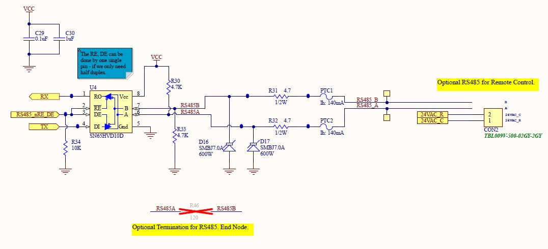
We have SN65HVD10D/RS485 Modbus Interface in our system.

  1. Line Voltage Fan with Modbus
  2. VFD (Motor Drive) with Modbus
  3. Control Board with Modbus

Hence, each part is capable of handling -7V to 12V as per datasheet.

The VFD has different Modbus part and is 5V line voltage with -7V to 12V range with its own fail safe biasing network. But since bus is capable of -7V to 12V, this shouldn’t matter also we have really max. three devices over this bus.

The Fan & VFD has isolated power supply for Modbus while the Control Board does not have any isolated power supply. We have only connected A & B of the Modbus to communicate between the units, basically digital ground is not common reference and it works fine.

Some of the scope captures are measured with the differential probe.

All these components sits inside one metal unit couple of feet away, returning to same electrical earth.

So far, we never had issue running the system and always ran fine around more than one year of testing inside labs and few month of test at various remote sites.

We are not sure if common ground is needed or not moving forward. Since one of the Fan & VFD are isolated, I tried shorting together all the grounds of fan, VFD & the control board but unfortunately, it damaged the Modbus port of the fan. May be we need to have isolated Modbus on control board to tie all the grounds together.

Below is additional note from TI App Engg, which also says common ground is not needed.

https://www.planetanalog.com/signal-chain-basics-84-why-rs485-does-not-need-ground-wires/#

Some of the online information mentions about the measuring the common mode voltage but here in this case we have three ground – Fan Ground, VFD Ground, Control Board Ground.

Can you please help to let me know your thoughts regarding the system? Is there any problem to operate?

  • Hi,

    In isolated systems, the digital signal is isolated. RS485 signal can be transmitted with shared ground or without common ground, depending on the ground potential difference. Like you mentioned, if the ground potential difference is between -7V and 12V, the transceivers work with no problem. If the ground is shared, usually it comes from one node. You can refer the section 11 of this app note for the detailed discussion.

    https://www.ti.com/lit/an/slla272c/slla272c.pdf

    I hope it makes sense to you. If you don't mind, you can share the schematic and I will help review it.

    Regards,

    Hao

  • Hi Hao,

    Thanks for responding so quickly. Sorry for not being clear in my first post. I meant -7V to +12V is typical SN65HVD10 transceiver rating capable of handling the range of this voltage across the devices. Since ground are not common, do you see any concern here? I never had a failure so far.

    Regarding Ground, As per below TI Engg (Thomas), this depends on the receiver internal resistors.

    https://www.planetanalog.com/signal-chain-basics-84-why-rs485-does-not-need-ground-wires/#

    If i need to measure GPD, which ground to consider if its not shared? I think this need to happen without differential probe and on the receiver side.

    Regarding the schematics, two of the components (Fan & VFD) are from 3rd party design. Also i just found out today that fan interface is not truly isolated, likely from the one fly back source inside the fan.

    On Fan side TI P/N: SN65HVD72D is used while the VFD side which has isolated side have Renesas P/N: ISL83080EIBZ-T.

    Below is from our design from Control Board, which don't have dedicated isolated power supply. But also not sure why shorting all grounds damaged the Fan Modbus Port.

    Thanks.

    BR,

    Aditya

  • Aditya,

    When you measure the GPD, please always refer to the same potential, like ground of a node. It depends on the potential difference and impedance, shorting two ground could generate a high current loop. Again RS485 works with -7V to 12V common mode difference. But you want to create a shared ground between nodes, you need to make sure there is no 'short' created. You can check out the Figure 9 of the app note I shared in last post for these different scenario.

    Regards,

    Hao 

  • Hi Hao,

    Thanks for your reply. The main concern i have is i know today our system works fine without common ground, may be because they are so close to each other, couple of feet apart. Shorting the ground we know it damages the Fan Modbus port. Can you please let me know, what is down side of running without ground? GPD difference should be more where system are far apart from each other, but in our case its powered on same electrical socket.

    If i need to measure GPD, can i measure ground of each part of the system like the VFD, Fan & Control board w.r.t A & B? But that will give me 3 different result, may be then i can consider worst one. Same can be repeated on multiple units. But again, not sure if this test is good test as they don't share ground,

    Since i need average of A & B, i like to use two same resistor say 10k and use center node w.r.t ground to measure the potential difference.

    Looking forward to hear from you soon.

    Thanks.

    BR,

    Aditya

  • Aditya,

    Yes, I think it's a good idea to reference to the common mode voltage of A/B for the ground measurement. I think you can turn one node on to bias the A/B while doing the measurement.

    Regards,

    Hao

  • Hi Hao,

    Thanks for your input. Since we don't have common ground in our system between the Fan, VFD & the Control Board. I have tested A & B w.r.t respective grounds of the components and got below data. Test has been repeated on three Units to confirm.

    Common Mode Voltage Measurement

    A & B had same resistor value of 10k. This A & B is common bus between the Fan, VFD & Control Board.

    Measurement was performed with Oscilloscope between Resistor common terminal & w.r.t respective Ground of respective component.


    FAN (Vdc), A+B to Fan Ground

    VFD (Vdc), A+B to VFD Ground

    Control Board (Vdc), A+B to Control Board Ground

    Unit 1

    1.2V

    2.5V

    1.8V

    Unit 2

    1.3V

    2.5V

    1.8V

    Unit 3

    2V

    2.5V

    1.8V


     Additional Notes:

    1. During the test no high amplitude noise was observed. Some noise was picked up by long ground wire, but was minimal within above mentioned limits.
    2. Tested with system running and ideal, voltage did not change.
    3. Unit 1 was only brand new unit. Unit 2 & Unit 3 has passed through lot of HDVP test, DLS & Biotron.
    4. Meter reading matched the oscilloscope.
    5. Fan Transceiver P/N: SN65HVD72D, VFD Transceiver P/N: ISL83080EIBZ-T, Control Board Transceiver P/N: SN65HVD10
    6. All these above Transceiver are capable of operating between -7V to 12V.

    Please help to provide your inputs.

    Thanks.

    BR,

    Aditya

  • Aditya,

    Thanks for you detailed measurement. Since little noise was observed and the results are consistent between the multimeter and scope, I think they're reliable. It looks like it's safe to running the system without shared ground.

    Regards,

    Hao

  • Thanks a lot Hao for all the support. It was really helpful.

    BR,

    Aditya