This thread has been locked.

If you have a related question, please click the "Ask a related question" button in the top right corner. The newly created question will be automatically linked to this question.

SN65HVD1780: Floating pin A voltage

Part Number: SN65HVD1780

Hi,

In receiver mode, if pin A is left unconnected / floating, what's its voltage?

Although I don't see any reference in the datasheet that pin A has a specific voltage in this case, however, I measure it to be around 1.7V, which doesn't seem to be coincidental.

I'm asking because if pin A has a specific voltage when floating, in my layout (and for the intended functionality) it's easier to leave it unconnected and connect only pin B .

Br,

Dimitris

  • The open-circuit failsafe will float the A pin to a voltage that results in the correct output when both A and B are floating, but there is no guarantee whatsoever what that voltage might be.

    If you want pin A to have a specific voltage (range), you have to force it externally. (A voltage divider is enough, but consider the 100 µA leakage current.)

  • Does this answer hold even if A is floating, but B is not floating?

    In other words, to be certain of A's voltage, would I have to force A externally in any case? I assume that the answer is "yes", but I would appreciate a confimation.

    At some point I thought that A's floating voltage has something to do with Vcc (i.e., something like Vcc/2), but I understand from your answer that this is not the case.

  • It would not make sense to allow the A and B pins to influence each other.

    I suspect there is an internal voltage divider that results in both A and B being near VCC/2, but this is not guaranteed, and you do not know what the tolerances are.

  • I have no intention to allow A and B to influence each other (I'm not sure how you came to this conclusion, it must have been something I said, but I don't know what exactly), I just want floating A to be around Vcc/2.

    Within this context, I also suspect that there is an internal voltage divider that results in floating A being near Vcc/2, which would be ideal for my design. The tolerances are not so important in my case (e.g., even a 50% deviation would be acceptable).

    Bottom line, this is exactly my question: is there an internal voltage divider that deterministically results in floating A having a voltage in the range of Vcc/2?

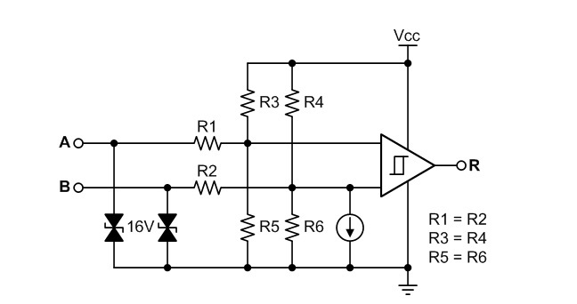
  • See RS-485 basics: the RS-485 receiver, which describes a different device, but I guess the basic architecture does not change. To be sure, measure the current at different external voltages.

  • Thank you very much Clemens, this link seems to provide a spot-on answer to my question.

    Thus, the only remaining question would be: what are the values for R1, R3 and R5 for this part?

    If someone from TI could answer this, it would conclude my search.

    Thank you very much!

  • Clemens,

    Thanks so much for your explanation.

    Antonis,

    The typical resistor values are:

    R1: 135k

    R2: 40k

    R3: 25k

    Please let me know if you have more questions.

    Regards,

    Hao

  • Dear Hao, 

    thank you very much for your reply.

    I believe that we are almost done. One problem: the notation of the resistors in your reply is not in line with Clemens' schematic.

    To avoid confusion, can you please confirm the following values in relation to the following schematic?

    • R1=R2=135kΩ
    • R3=R4=40kΩ
    • R5=R6=25kΩ

    Br,

    Dimitris

  • Dimitris,

    I'm sorry I didn't pay attention to the noting. Yes, the resistor values you showed are correct.

    Regards,

    Hao

  • Dear Hao and Clemens,

    thank you both very much, everything is clear now.

    Kind regards,

    Dimitris