This thread has been locked.

If you have a related question, please click the "Ask a related question" button in the top right corner. The newly created question will be automatically linked to this question.

TCAN1042HGV-Q1: Sending Transceiver to Standby Mode for Low Power Consumption

Part Number: TCAN1042HGV-Q1

Hi TI Team,

We are facing an issue with Standby mode for TCAN1042HGV-Q1.

INFO:- VCC=VIO= 5V(Isolated). TX,RX,STB driven via Optoisolators.

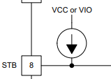
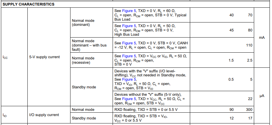
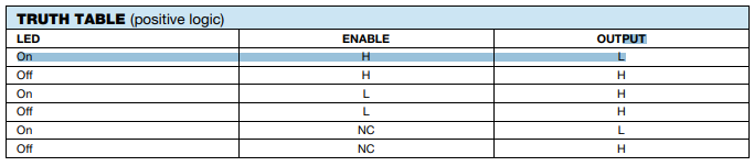
As per datasheet, transceiver shall enter low power consumption when STB pin is pulled to VCC.

Observation:- The STB pin is pulled HIGH if it is left floating but remains LOW if we try to drive it using opto-isolator.

We are not disconnecting the VCC or VIO supply when we want to send the transceiver to standby mode.

Can this be an issue?

Regards, 

Rohan

  • Hi Rohan,

    TCAN1042 has in integrated pull-up on the STB pin, so when it is left floating, the device will default to standby mode. This design is meant to keep the device in a low-power state if the controller is initially starting up or inactive (output is high impedance). If an open-drain output is used to drive this pin, I would still recommend an external pull-up resistor for faster transitions and increased noise immunity. 

    Does this answer your question? If I misunderstood your layout, please help by describing or illustrating how the STB is being driven by the optocoupler in your design. 

    Regards,
    Eric Schott

  • Hi Eric,

    This doesnt entirely solve the problem. But we do understand that if we leave STB floating it will always be pulled up to VCC resulting in transceiver always remaining in Low power mode.

    What issue we are facing is that the STB pin is never driven HIGH when we drive it through an optocoupler. We have pulled the pin HIGH to VCC externally. We have confirmed that the optocoupler is OK by driving another circuit.

    Hence our query on whether VCC for transceiver must be removed and the transceiver must only receive power via VIO pin to utilize STB functionality for devices with V suffix. 

    Please let me know if you need any other information.

    Regards,

    Rohan

  • Hi Rohan,

    The transceiver does not need to be unpowered in any way to achieve standby mode. This should be possible with both Vcc and Vio applied while the STB pin is driven above high-level input threshold (0.7*Vio). 

    It sounds like the external pull-up (if included) is having trouble pulling the STB line to this voltage on its own. Since the leakage through TCAN1042's standby pin should only be a few uA, I wonder if there are any other loads on this line. Is there any other device/component on this line other than the optocoupler, transceiver, and pull-up resistor? Please share a schematic or high-level diagram if possible - include resistor values. Would it also be possible to share the part number of the optocoupler? I'd like to know what it's output structure is.

    Regards,
    Eric Schott

  • Hi Eric.

    Attaching a section of datasheet where it has been mentioned VCC not needed in STANDBY mode and only VIO is needed. In our schematic VCC=VIO=5V always.

    I have attached a section of the schematic and marked the components that are not mounted with a red cross.

    Please let me know if you have any other queries. 

    Regards,
    Rohan

  • Hi Rohan,

    It doesn't appear that there's any way for the circuit to drive the STB pin of TCAN1042 to ground potential. When the optocoupler is not active, the external 3.3k-ohm pull-up resistor keeps the STB pin biased to ISO_5V. When the optocoupler is active, it similarly drives the line potential to ISO_5V. If the intent of the design is to put the transceiver into normal mode (STB pin low) when the optocoupler is engaged, pin 7 of the optocoupler can be connected to the GND_ISO net.

    Regarding the needed supply to TCAN1042; this device can be in standby mode while fully powered or when Vcc is not supplied. In other words, Vcc is not needed for standby mode, but it is not necessary to remove this supply for standby mode to be active. For normal operation, Vcc must be supplied for the transceiver to drive CAN communication. 

    Let me know if my comments above make sense or if I can clarify anything further.

    Regards,
    Eric Schott

  • Hi Eric,

    We are facing an issue of not being able to drive the STB pin to ISO_5V when the opto is switched off. We are able to drive the STB pin LOW when the optocoupler conducts. Attaching truth table for 6N137. We are using it in Enable HIGH configuration. Is there anything else that can force STB pin to remain LOW?

    Regards,

    Rohan

  • Hi Rohan, 

    There is no internal structure in TCAN1042 that would be attempting to keep thing input low. The weak pull-up should be attempting to default this state to high, so it's puzzling to hear that with this and the external pull-up the device still doesn't go to standby mode.

    Could you take scope shots of the STB net during a transition from the low-output state to the high-output state? I would like to see if there is any change in voltage in the different states and what the achievable voltage is in the high-state. 

    Regards,
    Eric Schott

  • Hi Eric,

    We were able to send the TCAN1042 into STANBY mode with VCC available. Thankyou for your support.