This thread has been locked.

If you have a related question, please click the "Ask a related question" button in the top right corner. The newly created question will be automatically linked to this question.

PCA9555: How to config I/O port as input or out

Part Number: PCA9555

Hi,

I checked datasheet and found the device I/O port can be programmed as input or output port.

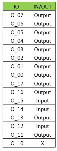
Could you please help to check if I can follow below table to set I/O port?

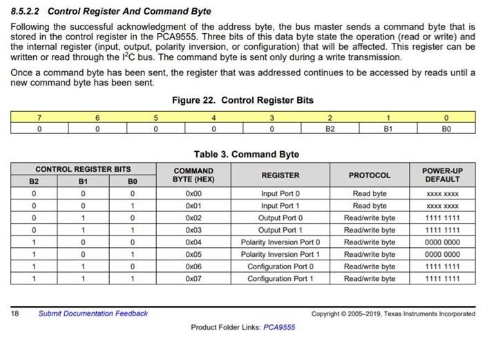
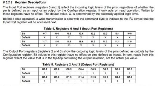
How to do that and what's the command?

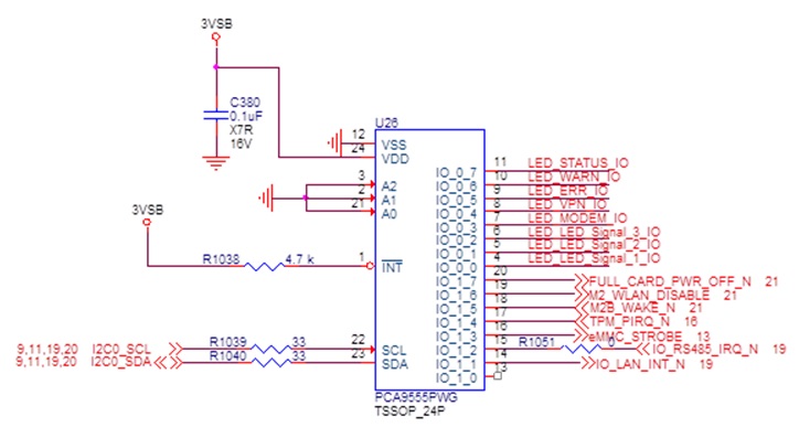
And please help to check below setting and schematic, if it's ok to work, thanks so much.

  • Hi Jim,

    To configure the IO pins of PCA9555 as either inputs or outputs, the configuration register (0x06, 0x07) must be written to. This can be done by writing four bytes to the device in the following order: Slave Address with the read/write bit cleared (0b'0100 AAA0)*, the command byte containing the configuration register (0x06), and the two bytes containing data on how the ports should be configured. These data bytes for the table you shared would be (0b'0000 0000) (0b'0011010X)**. An example of this can be seen in Figure 24 on the device's datasheet. 
    *The 'A' characters are determined by the state of the address pins. Based on your schematic, all of these values would be 0's. 

    The state of the output pins can be driven similarly by writing to the output port register (0x02, 0x03). Note that these registers can be written to individually (one port at time) using 3-byte sequences, or both ports can be written to in one sequence with a 4-byte message as described above (the address automatically increments after the first data byte). 

    The schematic looks good and I don't see any issue with any of the pins used for inputs/outputs. However, I would recommend tying the unused pin IO_1_0 to Vcc through a resistor. This will prevent the floating input from generating an interrupt due to noise. I recommend the resistor be used in the case that the pin is inadvertently configured as an output. 
    **I recommend leaving this pin configured as an input, so the 'X' in this byte should be a 1. 

    Let me know if this is clear and if you have any more questions.

    Regards,
    Eric Schott