This thread has been locked.

If you have a related question, please click the "Ask a related question" button in the top right corner. The newly created question will be automatically linked to this question.

TCA9509: I2C buffer issue

Part Number: TCA9509
Other Parts Discussed in Thread: CC1352R,

Hi Sir,

A customer have a TCA9509DGKR I2C buffer in his application,
but he is unable to get a response from the B side.
The problem is nearly identical to the one here:
e2e.ti.com/.../737445,
except he has A side connected to 3.3V.

He has verified through both oscilloscope and logic analyzer that his MCU is sending I2C signals and they are arriving at the A-side.
The MCU is a CC1352R。

I can not find any deviation in his schematic, VCCA<=VCCB-1V.

is the issue on pull-up resistors or running at 100kHz instead of 400kHz?

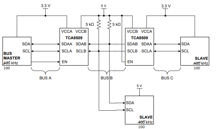
The attached diagram that represents the topology of customer's design.

  • Hello,

    The minimum switching frequency of the TCA9509 is 400 Khz. However, the MCU you chose is able to output at 400 Khz, so you could try increasing the frequency and seeing if the device works. You should also verify that there are no pull up resistors built in to the I2C pins on the MCU. I read through the datasheet and it looked like there weren't any.

    If that doesn't work there may be an issue with the pull up resistor sizing and the VOL of the device. We can look into that if that is the case.

    Best,

    Chris

  • Hi Chris,

    Thank you for your response.

    But after re-reading the datasheet I found section 9.3.3:

    "9.3.3 Standard Mode and Fast Mode Support
    The TCA9509 supports standard mode as well as fast mode I
    2C. The maximum system operating frequency will
    depend on system design and delays added by the repeater."

    I have not yet had the opportunity to try running at 400kHz, but based on this info it seems that either the problem lies elsewhere or the datasheet is incorrect. I did verify that there are no pull-up resistors between the CC1352R and the A side of the TCA9509, so I'm still stumped.

    I also find some threads mentioned that this device can work at 100KHz.

    The repeater itself is agnostic to the actual bus frequency.
    The limiting factor for the bus frequency is determined by the time-of-flight delay through the repeater.

    Thanks.

    Regards,


  • Hi Chris,

    Furthermore,

    I was able to take some more measurements, and found that turning the frequency up to 400kHz did not solve the problem.

    Looking with my oscilloscope, I see that the CC1352R is pulling the lines down to approx. 250mV. This does fall within the recommended operating conditions for VIL on the A side (0.3V MAX)

    I tried modifying my code as in e2e.ti.com/.../875117 to provide more drive strength (I even removed the PIN_PULLUP config), but the VIL A-side value did not change at all, and the B side was still inactive.

    I also removed the slave that is connected to the B side in my design, so it is just like Figure 6 in the datasheet, except the A sides both have 3.3V and the B sides have 5V. This still didn't change anything.

    I have changed the chip and checked all of my connections, so I'm truly at a loss here. Any suggestions would be much appreciated.

    Thanks.

  • Hi Frank,

    Could you post the scope shots here, or send them to my email at c-ayoub@ti.com? Please include all of Bus A and Bus B, so 4 channels at the same time.

    Best,

    Chris

  • Hi Chris,

    I will send you related scope shots via email.

    Thanks for your help.

  • Frank, Chris,

    Since this thread is now being handled offline, I will close this thread.

    Regards,

    Eric Hackett