This thread has been locked.

If you have a related question, please click the "Ask a related question" button in the top right corner. The newly created question will be automatically linked to this question.

THVD8000: Design questions

Part Number: THVD8000
Other Parts Discussed in Thread: ESD122

Dear *,

We want to use THVD8000 and have some design questions. Here are our specifications:

Max number of slave devices : 8

Bus Voltage 48V

Max Master output current 5A ( max power 240W)

Max Slave input current 1.25A

( in case 1-4 slaves max slave current is 1.25A ( 60W per slave) , 5slaves = 1A ( 48W per slave) , ... , 8slaves = 0.625A ( 30W per slave)) 

Communication speed : 0.5Mbps ( 5MHz carrier)

THVD8000 VCC = 3.3V

Questions:

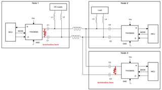
1) Termination ( we want to use termination)

1a) Master - where is the right place to put the termination on Master module? and what value should we use?

1b) Slave - where is he right place to put the slave termination ? and what value should we use?

2) Capacitor selection  per equation in DS

Is it ok to use 10nF 200V X7R 1206 ?

3) Inductor selection pre equation in DS

Is it ok to use 100uH 1.7A SRR1260-101M SRF=6MHz ?

4) The upper calculation is made if 8 slaves are connected to master device.

If we connect lower number of slaves to master  ( eg. 1, 2, ... , 6, 7) , and the connected salve has 10nF and 100uH will this then work?

We want to have one slave with same components that will work in following configurations:

1master -> 1slave

1master -> 2slave

...

1master -> 7slave

1master -> 8slave

5) Is there a point to add additional ESD diode  like ESD122 on Pin 6 and 7 of THVD8000

6) how can we estimate cable max length for the above specification ?

7) if the cable used is not twisted pair what kind of filtering should we use and where? Is it for this purpose ok to use CMC on power after the inductor on slave device?

Best Regards,

David.

  • David,

    There is a design guide you can check out. What's the communication distance? Please be aware of the cable loss with 5MHz signal.

    1) termination: please be sure the termination matches the cable impedance. The termination is recommended to place close to the bus pins (master or slave).

    2) capacitor: 10nF is about 12.6Ohm at 5MHz, which should be OK. If you see too much cable attenuation, you can choose a lower value.

    3) inductor: 100uF is about 3140Ohm at 5MHz. With 8 nodes, the total impedance is about 392Ohm, which is OK. You may find lower inductance also works in measurement. However I'm not sure if the 1.7A current rating is enough for the master.

    4) the same setup will work with smaller number of nodes.

    5) it depends on the system requirement. SM712 was used in the EVM. ESD122 is a 5V diode, which should be able to provide some level protection too.

    6) the maximum length for 5MHz is about 10 meter 20 awg cable.

    7) in many THVD8000 applications, the cable is not twisted pair. If the cable is short, the skew between the wires might be small. It's OK to use CMC on power.

  • Dear Hao,

    thank you for the replay.  Some additional questions

    1a) if the cable impedance is 100Ohm then i should either use 100Ohm diff termination or 2x50Ohm split termination is that correct?

    1b) can you please check the picture below it his is the right place for termination ? Mater has termination and only the last slave has termination is that corrct?

    2) I calculated the impedance Zc per equation on page 5 in Design guide and i got 3Ohm and not 12.6Ohm like you, how did you get 12.6Ohm?

    3) I calculated 100uH for 8 slaves, that also means that the master needs the same inductor value as the slaves? Yes you are correct regarding master it need higher current rated inductor.

    For the inductor selection is the SRF critical parameter when using f0 = 5MHz ?

    4) ok

    5) ok

    6)if low resistance cable is used then can we get more meters? Is the length of cable only dependent on f0 = 5MHz , or is also the power that needs to be considered ( we have max power of 240W) ?

    7) ok

    Best Regards,

    David. 

  • David,

    1a) Yes, either way would work. However two 50Ohm with a middle capacitor to ground shows better common mode rejection in measurement.

    1b) Correct. Please make the non-terminated nodes (node 2 in the example) as close to the main bus as possible (short stubs).

    2) You're correct. I calculated for 5nF then mistakenly double the impedance to get the value of 10nF.

    3) I would say the SRF is not critical, since it's high impedance which is what we want.

    6) The main cable length limit is the AC loss (insertion loss). Usually thicker cable has less loss.