This thread has been locked.

If you have a related question, please click the "Ask a related question" button in the top right corner. The newly created question will be automatically linked to this question.

TCA9509: 接上TCA9509时,导致主控时钟和数据的输出波形异常,但TCA9509的输出电平是正常

Part Number: TCA9509
Other Parts Discussed in Thread: TCA9617A

Hello,

when we use TI's IIC level conversion chip, we have the following exceptions:

Question:

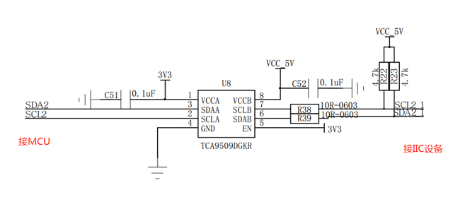
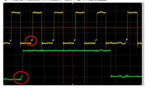
When TCA9509 is connected, the output waveform of the clock and data output of the master control is abnormal (as follows, yellow is the clock and blue is the data), but the conversion output level of TCA9509 is normal

The red circle is the abnormal part, which is stuck at about 10% and has lasted for 300nS.


Results of experiments done:

Remove the chip TCA9509 test controller output waveform: OK

Convert chip TCA9509 other side waveform: OK

Replace and remove pull-up resistors or resistance values on left and right sides: no improvement.

Please provide technical support, thank you.

  • Hello,

    What is the VOL of the Commander (formally Master) node?

    Can you give me a voltage measurement for the circled part of the waveform?

    Best,

    Chris

  • Hi Chris,

    Customer Ken's TCA9509 schematic is as follow, and the waveform measured on the A-side bus is as shown above. According to the TCA9509 Datasheet 10.1 Application Information, there is a pedestal at the ACK (see  Figure 1 in the datasheet), but the measured waveform by Ken is not consistent with the Datasheet. Customer Ken measured that there was a pedestal on each rising edge, what could be the cause of this?

    The pedestal voltage level within the red circle is about 750mV.

    Best Regards,

    Amy

  • It's more like the waveform in Figure 8 in the TCA9617A Datasheet, as shown below

  • Hi Amy,

    For buffered-output devices, when the buffer side is sitting at a low and is released the signal will rise to the buffered low. The device then holds the signal at this low until the the non-buffered side rises above the VIH threshold. Once this occurs the buffered side is then released and it will rise back up to the rail voltage. This is what causes the low level signal to look like a "pedestal". This occurs because I2C buffers are unable to determine signal directionality. 

    Let me know if this makes sense or if you have any further questions.

    Best,

    Chris