This thread has been locked.

If you have a related question, please click the "Ask a related question" button in the top right corner. The newly created question will be automatically linked to this question.

DS110DF111: LOCK PIN Issue

Part Number: DS110DF111

Dear Team,

Our Customer have a issue as below:

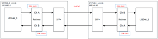
If the CDR Lock is successfully locked, the 16th pin LOCK signal should be high.

If the Lock signal is low, it should mean that CDR Lock failed.

Could you guide us if 16th pin LOCK signal is low, how to resolve CDR Lock failed issue?

Many Thanks,

Denny

  • Hi. Can you provide the values you are observing for the following retimer channel registers? 

    • 0x02, 0x03, 0x27, 0x28, 0x2D, 0x31

    Thanks,

    Rodrigo Natal

  • Here is the channel B register information.


    address

    value

    0x02

    0x04

    0x03

    0x00

    0x27

    0x00

    0x28

    0x00

    0x2D

    0x80

    0x31

    0x40


    root@localhost:~# i2cset -y 0 0x18 0xff 0x5

    root@localhost:~# i2cdump -y 0 0x18

    No size specified (using byte-data access)

         0  1  2  3  4  5  6  7  8  9  a  b  c  d  e  f    0123456789abcdef

    00: 00 00 04 00 00 00 00 00 00 00 10 0f 08 00 93 69    ..?.......???.?i

    10: 3a 20 a0 90 00 10 7a 25 40 23 00 03 24 00 e1 55    : ??.?z%@#.?$.?U

    20: 00 00 00 40 40 00 00 00 00 00 30 00 72 80 00 06    ...@@.....0.r?.?

    30: 00 40 11 88 bf 1f 33 0e 00 00 a5 29 e8 00 80 00    .@????3?..?)?.?.

    40: 00 40 80 50 c0 90 54 a0 b0 95 69 d5 99 a5 e6 f9    .@?P??T???i?????

    50: 00 00 a5 00 80 00 00 00 b0 95 ed d5 99 a5 e6 f9    ..?.?...????????

    60: 00 00 00 00 00 00 00 00 00 0a 44 40 00 00 00 00    .........?D@....

    70: 03 20 00 00 00 00 00 00 b0 95 e9 d5 99 a5 e6 f9    ? ......????????

    80: 00 40 80 50 c0 90 54 a0 b0 95 69 d5 99 a5 e6 f9    .@?P??T???i?????

    90: 00 00 50 00 80 00 00 00 b0 95 ed d5 99 a5 e6 f9    ..P.?...????????

    a0: 00 40 80 50 c0 90 54 a0 b0 95 69 d5 99 a5 e6 f9    .@?P??T???i?????

    b0: 00 00 99 00 80 00 00 00 b0 95 ed d5 99 a5 e6 f9    ..?.?...????????

    c0: 00 40 80 50 c0 90 54 a0 b0 95 69 d5 99 a5 e6 f9    .@?P??T???i?????

    d0: 00 00 a5 00 80 00 00 00 b0 95 ed d5 99 a5 e6 f9    ..?.?...????????

    e0: 00 40 80 50 c0 90 54 a0 b0 95 69 d5 99 a5 e6 f9    .@?P??T???i?????

    f0: 00 00 a5 00 80 00 00 00 b0 95 f9 d5 99 a5 e6 05    ..?.?...????????

  • Dear Team,Here is the channel B register information.


    address

    value

    0x02

    0x04

    0x03

    0x00

    0x27

    0x00

    0x28

    0x00

    0x2D

    0x80

    0x31

    0x40


    root@localhost:~# i2cset -y 0 0x18 0xff 0x5

    root@localhost:~# i2cdump -y 0 0x18

    No size specified (using byte-data access)

         0  1  2  3  4  5  6  7  8  9  a  b  c  d  e  f    0123456789abcdef

    00: 00 00 04 00 00 00 00 00 00 00 10 0f 08 00 93 69    ..?.......???.?i

    10: 3a 20 a0 90 00 10 7a 25 40 23 00 03 24 00 e1 55    : ??.?z%@#.?$.?U

    20: 00 00 00 40 40 00 00 00 00 00 30 00 72 80 00 06    ...@@.....0.r?.?

    30: 00 40 11 88 bf 1f 33 0e 00 00 a5 29 e8 00 80 00    .@????3?..?)?.?.

    40: 00 40 80 50 c0 90 54 a0 b0 95 69 d5 99 a5 e6 f9    .@?P??T???i?????

    50: 00 00 a5 00 80 00 00 00 b0 95 ed d5 99 a5 e6 f9    ..?.?...????????

    60: 00 00 00 00 00 00 00 00 00 0a 44 40 00 00 00 00    .........?D@....

    70: 03 20 00 00 00 00 00 00 b0 95 e9 d5 99 a5 e6 f9    ? ......????????

    80: 00 40 80 50 c0 90 54 a0 b0 95 69 d5 99 a5 e6 f9    .@?P??T???i?????

    90: 00 00 50 00 80 00 00 00 b0 95 ed d5 99 a5 e6 f9    ..P.?...????????

    a0: 00 40 80 50 c0 90 54 a0 b0 95 69 d5 99 a5 e6 f9    .@?P??T???i?????

    b0: 00 00 99 00 80 00 00 00 b0 95 ed d5 99 a5 e6 f9    ..?.?...????????

    c0: 00 40 80 50 c0 90 54 a0 b0 95 69 d5 99 a5 e6 f9    .@?P??T???i?????

    d0: 00 00 a5 00 80 00 00 00 b0 95 ed d5 99 a5 e6 f9    ..?.?...????????

    e0: 00 40 80 50 c0 90 54 a0 b0 95 69 d5 99 a5 e6 f9    .@?P??T???i?????

    f0: 00 00 a5 00 80 00 00 00 b0 95 f9 d5 99 a5 e6 05    ..?.?...????????

  • Dear Team

    Here is the channel B register information.


    address

    value

    0x02

    0x04

    0x03

    0x00

    0x27

    0x00

    0x28

    0x00

    0x2D

    0x80

    0x31

    0x40


    root@localhost:~# i2cset -y 0 0x18 0xff 0x5

    root@localhost:~# i2cdump -y 0 0x18

    No size specified (using byte-data access)

         0  1  2  3  4  5  6  7  8  9  a  b  c  d  e  f    0123456789abcdef

    00: 00 00 04 00 00 00 00 00 00 00 10 0f 08 00 93 69    ..?.......???.?i

    10: 3a 20 a0 90 00 10 7a 25 40 23 00 03 24 00 e1 55    : ??.?z%@#.?$.?U

    20: 00 00 00 40 40 00 00 00 00 00 30 00 72 80 00 06    ...@@.....0.r?.?

    30: 00 40 11 88 bf 1f 33 0e 00 00 a5 29 e8 00 80 00    .@????3?..?)?.?.

    40: 00 40 80 50 c0 90 54 a0 b0 95 69 d5 99 a5 e6 f9    .@?P??T???i?????

    50: 00 00 a5 00 80 00 00 00 b0 95 ed d5 99 a5 e6 f9    ..?.?...????????

    60: 00 00 00 00 00 00 00 00 00 0a 44 40 00 00 00 00    .........?D@....

    70: 03 20 00 00 00 00 00 00 b0 95 e9 d5 99 a5 e6 f9    ? ......????????

    80: 00 40 80 50 c0 90 54 a0 b0 95 69 d5 99 a5 e6 f9    .@?P??T???i?????

    90: 00 00 50 00 80 00 00 00 b0 95 ed d5 99 a5 e6 f9    ..P.?...????????

    a0: 00 40 80 50 c0 90 54 a0 b0 95 69 d5 99 a5 e6 f9    .@?P??T???i?????

    b0: 00 00 99 00 80 00 00 00 b0 95 ed d5 99 a5 e6 f9    ..?.?...????????

    c0: 00 40 80 50 c0 90 54 a0 b0 95 69 d5 99 a5 e6 f9    .@?P??T???i?????

    d0: 00 00 a5 00 80 00 00 00 b0 95 ed d5 99 a5 e6 f9    ..?.?...????????

    e0: 00 40 80 50 c0 90 54 a0 b0 95 69 d5 99 a5 e6 f9    .@?P??T???i?????

    f0: 00 00 a5 00 80 00 00 00 b0 95 f9 d5 99 a5 e6 05    ..?.?...????????


    BR,

    Denny

  • Below is full decoding for channel register 0x02.

    The customer is observing 0x02 = 0x04. based on this value:

    • PPM check is not being met
    • signal quality and/or amplitude is not enough for lock

    I would recommend to,

    1.  try disabling PPM check to see if lock is then achieved
    2. Try increasing the amplitude of input signal to the retimer


    Address

    (Hex)


    BITS

    DEFAULT VALUE (Hex)


    MODE


    EEPROM


    FIELD NAME


    DESCRIPTION

    2

    7:0

    0x0

    R

    N

    cdr_status

    CDR Status [7:0]

    Bit[7] = PPM Count met

    •     1: The data rate is within the specified PPM tolerance (typically around ±1000 ppm unless specified otherwise in Reg 0x64).

    •     0: Error: PPM tolerance exceeded.

    Bit[6] = Auto Adapt Complete

    •     1: CTLE auto-adaption is complete.

    •     0: CTLE auto-adaption in progress.

    Bit[5] = Fail Lock Check

    •     1: Signal quality and amplitude level is not sufficient for lock.

    •     0: Signal quality and amplitude level is sufficient for CDR lock.

    Bit[4] = Lock

    •     When asserted, indicates CDR is locked to the incoming signal.

    Bit[3] = CDR Lock

    •     When asserted, indicates CDR is locked to the incoming signal (same status as bit 4).

    Bit[2] = Single Bit Limit Reached

    •     1: Number of bit transitions to acquire CDR lock has been met.

    •     0: Not enough bit transitions within the CDR lock time window to declare lock.

    Bit[1] = Comp LPF High

    •     1: Data rate exceeds the VCO upper limit, based on loop filter comparator voltage.

    •     0 = Data rate is within VCO upper limit.

    Bit[0] = Comp LPF Low

    •     1: Data rate is below the VCO lower limit, based on loop filter comparator voltage.

    •     0 = Data rate is within VCO lower limit.

    Thanks,

    Rodrigo

  • Dear Team 

    the costumer reply as below

    I tried to disable PPM check with the following command, it seems CDR is still unlock

    root@localhost:/mnt/ramfs# i2cset -y 0 0x18 0xff 0x5

    root@localhost:/mnt/ramfs# i2cget -y 0 0x18 0x2f

    0x06

    root@localhost:/mnt/ramfs# i2cset -y 0 0x18 0x2f 0x2

    root@localhost:/mnt/ramfs# i2cset -y 0 0x18 0xa 0x1c

    root@localhost:/mnt/ramfs# i2cset -y 0 0x18 0xa 0x10

    root@localhost:/mnt/ramfs# i2cget -y 0 0x18 0x2f

    0x02

    root@localhost:/mnt/ramfs# i2cget -y 0 0x18 0x2

    0x00

    root@localhost:/mnt/ramfs# i2cget -y 0 0x18 0x2

    0x04

    For the amplitude test, could you share the corresponding command to us increasing the amplitude of input signal to the retime?

    BR,

    Denny

    • Can you provide a detailed description of your test setup?
    • What is the approximate retimer input channel insertion loss?

    Thanks,

    Rodrigo

  • Dear Team

    the costumer reply as below :


           Here is the test scenario.

           As our design is based on NXP LS1046 RDBwe did not evaluate the input channel insertion loss before.

           Could you provide more information about how to evaluate the parameter?

    Many Thanks,

    Denny

  • Hi Denny,

    Most likely this SFP+ ingress channel is low Insertion loss. One way to estimate the loss of a channel is to measure the signal electrical amplitude at its output for both high frequency data pattern (e.g. 1010) and low frequency pattern (e.g. 1111111100000000), then calculate the dB ratio of the two amplitude values.

    For your case I would recommend to apply the following settings on CHB of the fail retimer to force CTLE = 0x00
    (i.e. lowest boost setting.)


    STEP

    SHARED/CHANNEL REGISTER SET

    OPERATION

    REGISTER ADDRESS [HEX]

    REGISTER VALUE [HEX]

    WRITE MASK [HEX]

    COMMENTS

    1

    Channel

    Write

    31

    00

    60

    Set Adapt Mode 0.

    2

    Channel

    Write

    03

    00

    FF

    EQ=0x00, Select the right value depending on the channel loss.

    3

    Channel

    Write

    3A

    00

    FF

    Same as Reg_0x03

    4

    Channel

    Write

    40

    00

    FF

    Same as Reg_0x03

    5

    Channel

    Write

    2D

    08

    08

    Enable overriding the EQ setting

    from 0x03 register setting(Need to set for DF111s).

    Thanks,

    Rodrigo Natal

  • Dear Team 

    The custermer have completed the bypass retimer, and then connect the SERDES from the MAC to the optical module through a jumper wire.
    Press the reset button, and then turn on the power 30 times each time - ping connected

    The preliminary conclusion is not clear, and it has a lot to do with the retimer. We have measured the power supply ripple of the retimer and input 25MHz clock and compared it with the demo board.
    The measurement data is as follows.

    Many Thanks,

    Denny

  • Dear team

    the costumer reply as below :

    I tried to force CTLE=0x00, still got the issue.

    Many Thanks,

    Denny

  • Hi, see additional suggestions below.

    1. Can you confirm that the input data rate to the retimer is 10.3125Gbps?
    2. For the case where issue is observed after SFP+ hot plug, if you perform retimer CDR reset and release is the channel able to lock?
      •  

        STEP

        SHARED/CHANNEL REGISTER SET

        OPERATION

        REGISTER ADDRESS [HEX]

        REGISTER VALUE [HEX]

        WRITE MASK [HEX]

        COMMENT

        1

        Channel

        Write

        0A

        0C

        0C

        Assert CDR reset.

        2

        Channel

        Write

        0A

        00

        0C

        Release CDR reset.

    3. If you disable SBT check by setting channel register 0x0C[3]=0 does the retimer channel acquire CDR lock?

    Thanks,

    Rodrigo Natal

  • Dear  Rodrigo Natal

    Could you discuss offline, i have sent mail to you.

    many thanks

    denny