A related question is a question created from another question. When the related question is created, it will be automatically linked to the original question.
If you have a related question, please click the "Ask a related question" button in the top right corner. The newly created question will be automatically linked to this question.
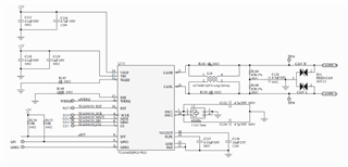
All power and bus related items look good here. Decoupling and filtering capacitors are in place and valued appropriately, and the bus has implemented split termination with other common peripherals in correct locations.
My concern lies with the circuit for the crystal oscillator. How were the load capacitors selected for this design? Was this based on the capacitance of the board and crystal parameters? It may be good to check with the crystal manufacturer to ensure that this load is not too small - which may cause overstress of the device as the voltage peeks may be too large, decreasing device lifetime.
The value of the bus capacitors will depend on how large of a system this is being implemented in and how much filtering/protection is needed at each node. Typically we recommend values between 10pF to 150pF. Smaller values will need to be used for larger systems to limit the total capacitance added to the overall CAN bus. Similar limitations will apply to systems that make use of high data rates as the dominant to recessive transition will be slowed by this extra bus capacitance.