A related question is a question created from another question. When the related question is created, it will be automatically linked to the original question.
If you have a related question, please click the "Ask a related question" button in the top right corner. The newly created question will be automatically linked to this question.
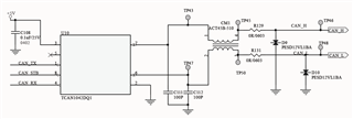
All logic signals (TXD, RXD, STB) are routed to the MCU.
VCC is properly decoupled.
CANH and CANL pins have choke, filter capacitors, and TVS diodes. One thing I noticed is the placement of the filter capacitors, I tend to see them after the common-mode choke (other side closer to the rest of the CAN bus) rather than between the choke and the pin. This way isn't wrong, I just wanted to point that out.
I also noticed no termination on the bus pins. Can you explain why?