


Other Parts Discussed in Thread: TPS2553
Hi, I'm interested in using the TPD3S014 as a current-limiting and reverse-blocking mechanism to allow a device to be powered from an AC power adapter or a USB port (with limited current capability). I can't afford to use a proper purpose-built part like the MAX8895 because CSP or WSP footprints are too tiny for the technology level I'm targeting.
The intention is that if AC power (from a 24V wall adapter) is connected, a P-channel FET will cut off the USB power rail. The output of the part is tied to the output of a 5V regulator attached to the 24V rail. It would appear that with the IN and EN pins tied together, this will effectively cut it off and also prevent the AC-powered 5V rail from providing power to the USB rail. One thing I was concerned about was the "output discharge" function when the part is disabled/UVLO, but it appears that once the IN pin is discharged, the output discharge circuit will essentially go high-Z, is that right?
Here is a schematic of what I'm trying to do:
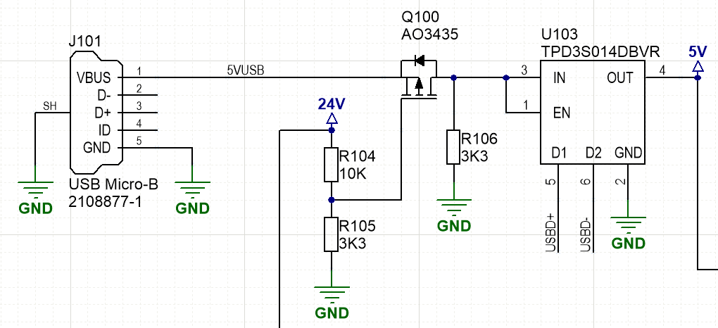
I put the switch between the USB input and the TPD3S014 because in the case that the USB bus voltage is lower than the AC-derived 5V regulator's output, I don't want my 5V regulator to sink into it through the body diode of the P-FET.
How well, if at all, should this work? What might I be missing?
