This thread has been locked.

If you have a related question, please click the "Ask a related question" button in the top right corner. The newly created question will be automatically linked to this question.

TPD6S300: VPWR supply

Part Number: TPD6S300
Other Parts Discussed in Thread: HD3SS3220, TPD2S300

Is there any limitation on the VPWR +3.3V supply ? Is there factor(besides the current consumption) that I have to be aware of if I am powering the VPWR from my system +3.3V ? I have a voltage regulator that is supplied by VBUS via a TPD1S514-1 (giving 23.5 mS ramped softstart) that is to supply this +3.3V 

  • Hi Shmuel,

    As long as the PD Controller is also powered around the same time as the TPD6s300, I don't believe I see an issue here.

    If this answers your question, PLEASE select  This resolved my issue. 

  • On one port the TPD6S300 is being used to protect the CC lines connected to a TUSB320LA that is powered directly by the VBUS_SYS output of the TPD1S514-1 (via a diode) and my +3.3V (which is powered via the VBUS_SYS output of the TPD1S514-1) has a rise time : 1.62mS MAX

    On the 2nd port the TPD6S300 is being used to protect the CC lines connected to a HD3SS3220 that is powered directly by the VBUS_SYS output of the TPD1S514-1 (via a diode) for its VDD5 lines and this +3.3V for the VCC33 line - my +3.3V (which is powered via the VBUS_SYS output of the TPD1S514-1) has a rise time : 1.62mS MAX
  • Hi Shmuel,

    I'm a bit confused as to how both USB ports are connected. Could you draw up a block diagram showing the devices and connections, as well as your power source?

    One of the ports would need power. You can connect a buck/ldo directly to the power source of one of the ports.
  • Dear Aramis P. Alvarez,

    Sorry I wasn't clear enough.

    I have 2 USB ports.

    The first port I am using a TPD1S514-1 to protect my system from over voltage on VBUS. The output voltage - VBUS_SYS - is being used to power my TUSB320LA (VDD) and is also used to connect to its VBUS_DETECT. The CC lines (and USB 2.0 signals) are protected via a TPD6S300 whoes VPWR I need to power at +3.3V. I have a +3.3V supply that comes from a regulator that is powered by the VBUS_SYS.

    My 2nd port is completely isolated from the first and has a similar configuration as the first but I am using a HD3SS3220 (instead of TUSB320LA). I have a seperate TPD1S514-1 with its own VBUS_SYS output that is powering the HD3SS3220 (VDD5). This VBUS_SYS is also connected to the VBUS_DET of the HD3SS3220. There is a VCC33 supply on the HD3SS3220 that I need to connect the output of my +3.3V regulator I mentioned above. I am using a 2nd TPD6S300 to protect the CC lines etc. This is being powered by the +3.3V regulator.

    Note I am using a ORing diode to combine the power (VBUS_SYS) from both ports and this combined power is being using to supply my +5v to +3.3V regulator.

    My +3.3V regulator as has a rise time : 1.62mS MAX
  • Hi Shmuel,

    Thank you for explaining your system to me. Could you possibly draw up a system block diagram and attach? This will greatly help me look at your system to determine if I see any red flags. Thanks in advance.
  • Dear Aramis P. Alvarez,

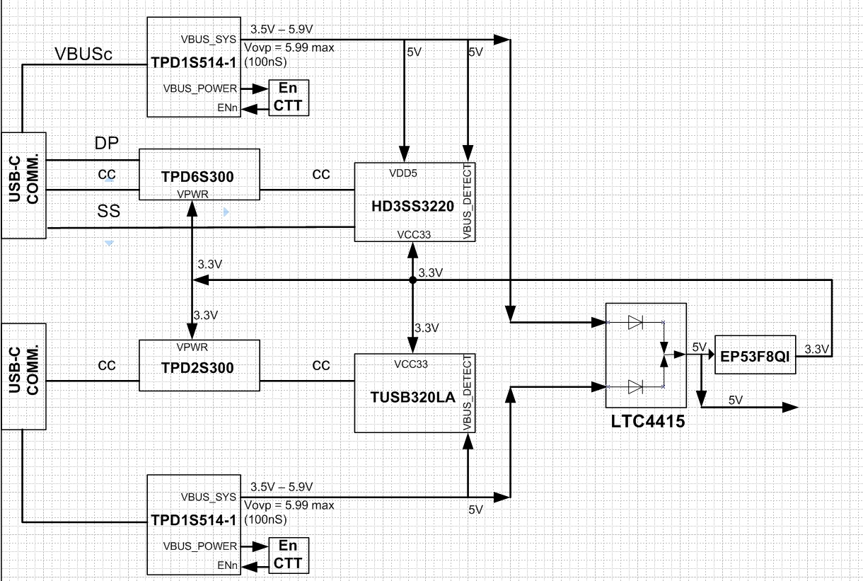
    Below is a block diagram of my Type C interface. My biggest concern is the Vovp = 5.99V of the TPD1S514-1 however it is only for 100nS. There is a high possibility that the user might plug in a USB-C supply that will give 20V initially but it appears that the VBUS_SYS will only be > 5.95V max for max 100nS so I think the concern is reduced a lot ?  

    The other thing that needs to be double checked is the powering of the 3.3V supplies of the TPD6S300, TPD2S300, TUSB320LA and the HD3SS3220 and any special powering sequencing that may interfere with proper operation. 

    What do you thjink ?

    Bets regards

    Shmuel 

  • Hi Shmuel,

    If you have a 3.3V regulator from a device (such as the TPD1Sxxxx) I would recommend to use this supply to power the TPD6/2s300. If not, then I recommend having a 3.3V buck converter, coming off VBUS, to supply our device. I hope this helps :-)

    If this answers your question, PLEASE select  This resolved my issue. 

  • Dear Aramis P. Alvarez,

    Thank you for your response. What would be wrong with getting the supply from the EP53F8QI I outlined in block diagram ? If I had to supply the +3.3V from a DC\DC from the VBUS then I would need 2 x +3.3V regulators one for each port (since my device could be powered from either port) which would complicate the design greatly ! 

    Best regards

    Shmuel 

  • Hi Shmuel,

    The power connections seem ok to me, but we recommend to power up our protection device around the same time as your type-c/pd controller. Are you using "Dead battery mode" on the TPD6s300? If so, I believe your connections are fine :-)

    If this answers your question, PLEASE select  This resolved my issue 

  • Dear Aramis P. Alvarez,

    We have configured "Dead battery mode" on the TPD6s300 (by tying RPD pins to C_CC pins) and the TPD2S300 already has "Dead battery mode" built in as far as I understand right ? Thus this type of configuration should be fine ?

    Best regards

    Shmuel
  • Hi Shmuel,

    You're understanding is correct about the "dead battery mode's", and this configuration should be fine :-)

    If this answers your question, PLEASE select  This resolved my issue. 

  • Thank you for all your Great help !!!!!